10
S-PARK
- rev. 1.1_06_2020
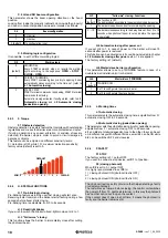
3.6.6
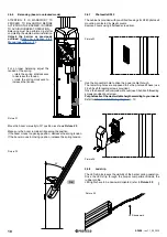
Balancing (boom in unlocked mode)
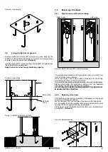
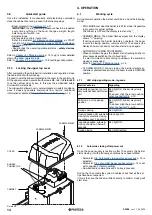
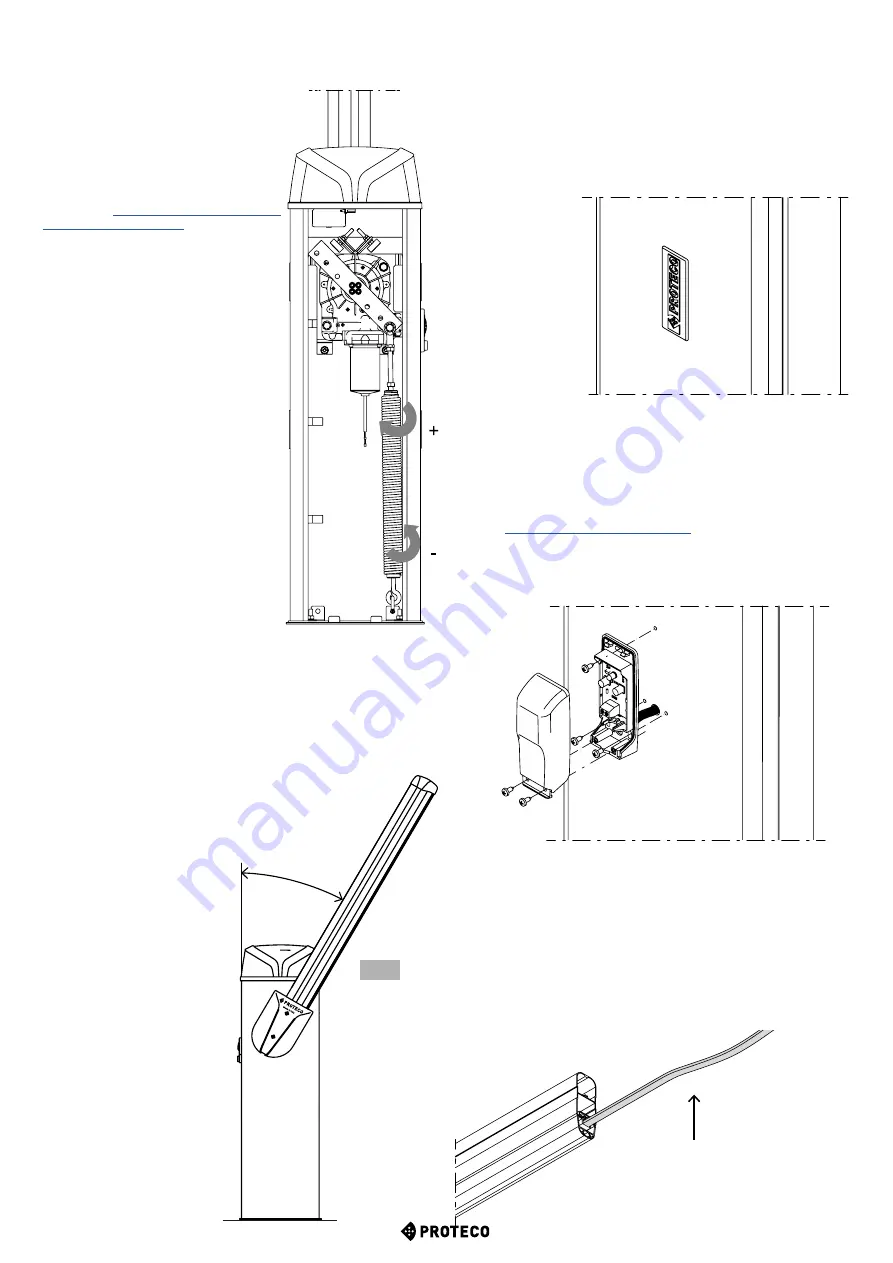
Picture 22
30°
OK
3.6.7
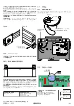
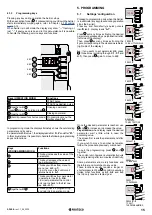
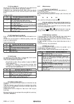
Photocells RF40
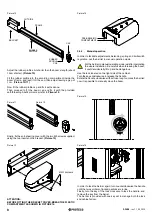
The cabinet is provided with pre-drilled housings for RF40 photocell
mounting, protected by plastic covers.
Remove covers using a flathead screwdriver.
Use the big central hole to drive the power cable through.
The remaining holes are supposed to fix the photocell’s base (use
3,5x9,5 self-threading screws provided).
Once the base is fixed complete with cover (use 3,5x9,5 self-threading
screws provided) and screw.
Put photocells at the most suitable heigth according to your needs.
Refer to
p. 12.
Picture 23
Picture 24
3.6.8
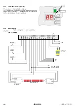
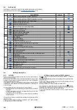
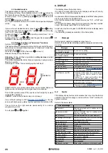
Led strip
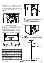
The LED strip increases the visibility of the barrier during operation.
Drive the LED strip through the proper compartment inside the
rubber profile.
LED lights have to be downward oriented, refer to
Picture 25
Picture 25
LED downward
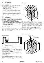
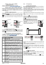
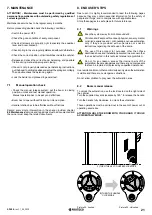
Picture 21
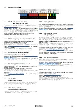
For a proper balancing adjust the
tension of the spring:
• rotate the spring anticlockwise
to decrease the tension
• rotate the spring clockwise to
increase the tension.
Move the boom manually to 30° position, as shows
Picture 22
.
Make sure the boom remains still keeping the position.
If the boom moves to opening position , decrease the spring tension.
If the boom moves to closing position, increase the spring tension.
ATTENTION: IT IS MANDATORY TO
PROCEED TO BALANCING BEFORE
ACTIVATING THE BARRIER, IN ORDER
TO AVOID INCORRECT OPERATION.
Balancing must be performed just after
completing the whole barrier installation.
Unlock the barrier as previously
outlined (


