11
S-PARK
- rev.1.1_06_2020
+ - + -
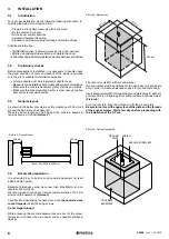
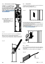
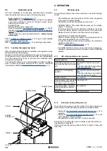
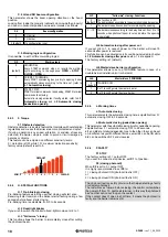
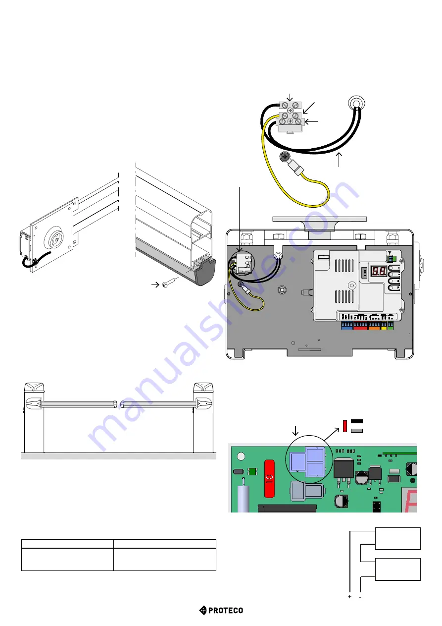
If the LED strip struggles when passing through the compartment,
put a little oil to facilitate the insertion.
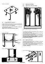
Then drive the power wire through the bracket, before fitting the
boom.
Fix the wire exactly as shown in
Picture 27
, then drive it through one
of the cabinet’s holes, the most suitable one according to installation
features and proceed to wiring (refer to Chapter 3.7).
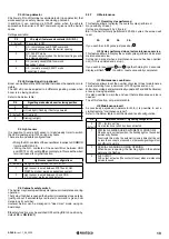
Fix the cap to the rubber profile using the provided 3,5x19 screw.
(Picture 26
)
ATTENTION
: If for any reason the LED strip has been cut, put
silicone on the cut side before fitting the cap to the rubber profile.
3.6.9
Boom accessories
If you plan to fit the boom with any accessory, do it before proceeding
to programming.
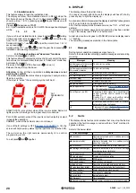
3.6.10 Mirror barriers (TWINNING)
Picture 27
Picture 26
SELF-THREADING
SCREW 3,5X19
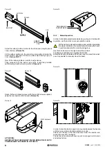
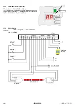
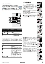
Mirror barriers installed on the same drive way (as shows the above
picture) can work simultaneously if wired together on TWIN terminals.
The master barrier will command the slave barrier; slave barrier
may only stop if detecting an obstacle during operation.
Any safety and command devices shall be wired to the master
barrier only.
As well the master barrier is the only one that shall perform pede-
strian opening, terminal START2.
Master barrier settings
Slave barrier settings
Set function H.6 to 1
Perform C.1 programming
Set function P.2 to 0
Set function H.6 to 2
Refer to
Chapter 3.8.1.9 DAT + GND (TWIN
), p. 25.
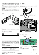
3.7 Wirings
3.7.1
Main power 230V
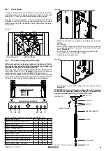
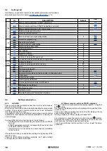
The main power terminal is located on the upper side of the cabinet,
close to control unit:
MAIN POWER
230 Vac
ATTENTION: factory pre-wiring,
do not make any alteration.
PHASE
GROUND
COMMON
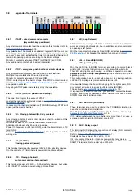
3.7.2
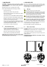
Back-up batteries
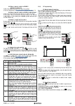
BATTERY
CONNECTOR
Use two 12V / 1,2Ah batteries wired
in series;
Wire cable + (red) to red faston
Wire cable – (black) to black faston.
Grey faston remains free.
Battery 12V dc
1,2 Ah
Battery 12V dc
1,2 Ah


