8
S-PARK
- rev. 1.1_06_2020
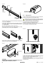
BRACKET
Picture 10
FRAME
RUBBER
PROFILE
RUBBER
PROFILE
CAP
CAP
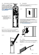
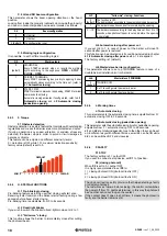
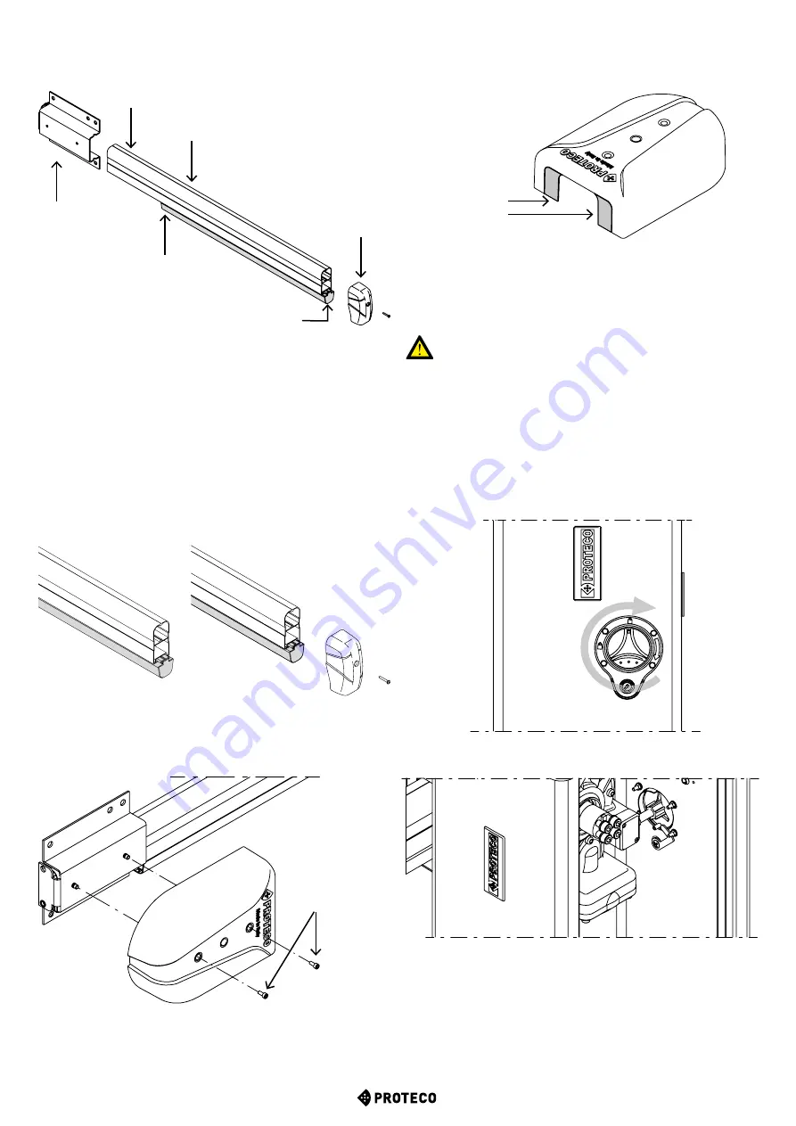
Adjust the rubber profile a bit shorter than the boom’s length (about
19cm shorter).
(Picture 10)
Fit the rubber profile into the according compartment inside the
boom’s frame, and lead it till the end, then adjust leaving a gap of
1 cm. (
Picture 10/11)
Now fit the rubber profile cap and fix it with silicone.
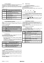
Then proceed to fit the boom cap and fix it with the provided
self-threading 3,5x32mm screw, refer to
Pitcure 12
.
Picture 11
Picture 12
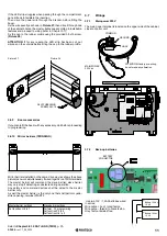
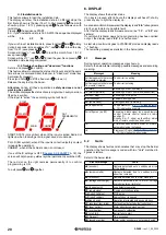
Finally, fix the anti-shearing cover with the two M5 screws supplied,
using the two inserts on the bracket.
(Picture 13)
Picture 13
M5X16
screws
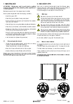
ATTENTION:
BEFORE FITTING THE BRACKET COVER, BREAK THE PLASTIC
COMPARTMENT AS SHOWN IN PICTURE 14.
Picture 14
3.6.3
Manual operation
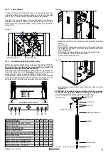
In order to facilitate adjustments, balancing, spring and limit switch
regulation, put the barrier in manual operation mode.
Put the barrier to manual operation mode just after completing
the whole installation. Be carefull when releasing the boom,
it could accidentally lift up and be dangerous.
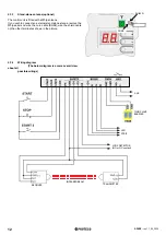
Use the lock located on the right side of the cabinet.
Turn the key anticlockwise to release the handle.
Rotate the handle clockwise all the stroke long to unlock the barrier:
now it is possible to manually move the boom.
Picture 15
Picture 16
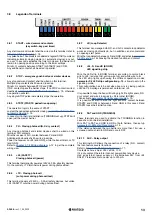
In order to lock the barrier again, turn counterclockwise the handle
until the two symbols of locked padlock are in line.
Finally, turn the key of the lock clockwise to lock the handle, and
remove the key from the barrel.
The barrier is provided with one key set to manage both the lock
and cabinet's door.
PRE-BREAKING
COMPARTMENT
CUT SIDE


