background image


P. 6


Installation Guide 


Return to the engine bay and route the tach and hood pin wire to their corresponding connections.  


Solder the engine compartment wire once the connections are made. When the solder has cooled, the 

connections are then individually taped up, to isolate them.  


Use your DMM to verify that your ground location is good before grounding the module.  


The last step before programming is to power up the module. Replace the power fuses on the power wire 

fuse holders. The module will click twice to confirm the power-up. 


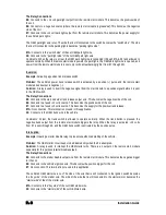
A basic introduction to the Relay  

What is a relay? 
A relay is a switching device that responds to a small current or voltage change by activating switches or other 

devices in an electric circuit such as an electromagnetic switch, remote controlled switch, a switching device.  
Why are relays used? 
Relays can have several purposes in remote car starter installations. They are mainly used for isolation, 

inversion, interruption, strengthening current, and for powering multiple wires from one source safely.  
How does a relay work? 
The basic relay consists of a coil and a set of contacts. The most common relay mechanism is the 

electromagnetic mechanism. When voltage is applied to the coil, current passes through the wire and creates a 

magnetic field. This magnetic field pulls the contacts together and holds them until the current flow in the coil 

has stopped.  

Relays come in all varieties and types, but for the applications that concern us, we will concentrate on the 

single pole double throw (SPDT) 12 volts relay. 
Naming Convention 
Usually the relay’s manufacturer will include an electrical diagram on the relay displaying the role of each 

terminal and how they interact with each other. 

These terminal numbers are standard, and can be used with any SPDT relay. 

85 & 86: The coil. These inputs energize the coil when one is +12 volts, and the other is negative. They are 

usually non-polarized, so it does not matter which one is positive (+) or negative (-).  

87: Normally Open (N/O). When the coil is energized, 87 is connected to 30. 

87A: Normally Closed (N/C). When the coil is at rest, 87A is connected to 30.  

30: Common. When the relay is at rest, 30 is connected to 87A, when the coil is energized, it is then moved 

and makes contact with 87. (Note: in a SPDT relay, 30 can never be connected to 87 and 87A at the same 

time, 30 is connected to either 87 or 87A) 
What happens? 
When there is no voltage across the coil (terminals 85 and 86), the relay's movable contact arm (connected to 

terminal 30) is held, by spring tension, against terminal 87A (normally closed circuit). 


When 12 volts is applied to the coil (terminals 85 and 86), the arm (connected to terminal 30) is pulled by the 

electromagnet (coil) so that it physically connects to terminal 87 (normally open circuit). 


When 12 volts is applied to the coil (terminals 85 and 86), the arm (connected to terminal 30) is pulled by the 

electromagnet (coil) so that it physically connects to terminal 87 (normally open circuit). 


Remember, there is no polarity on a relay’s coil. This means that you may apply positive from the battery to 

either terminal 85 or 86, and then ground the other terminal to activate the relay. In other words, you may use 

either a positive or negative trigger to energize the relay. 


Keep in mind, when the relay is energized, if the positive or the ground connection on the coil is broken, the 

arm switches the connection between 30 back from 87 to 87a. 

Summary of Contents for CT-5072

Page 1: ...arefully before beginning any work Warning Before installing the unit if installing on a vehicle with a manual transmission test that the OEM Door Switch contacts of the vehicle work well and that the Parking Brake system operates properly If installing on a vehicle with an automatic transmission test that the vehicle does not start when the gearshift lever is in the Drive position If it starts in...

Page 2: ...g 19 Tach jumper settings 19 Multi speed Tach Programming Procedure 19 Auto Tach Programming Procedure 19 Siren Horn Timing Adjustment 20 Setting the unit into Ready Mode 20 Arming and disarming of the System 21 Installation programmable Features 22 Ignition Controlled Door Locks 22 Secure Lock 22 AUX 3 ouput 22 AUX 2 23 Safe Start 23 Engine Run Time 23 Idle Mode 23 Turbo Mode 24 Vehicle Type Gas ...

Page 3: ...uded in the kit 1 Control unit 1 Plug in dual shock sensor 2 4 button remote 1 Siren 1 Antenna and interconnect cable 1 Parts bag 1 Harness Kit 1 Wiring diagram 1 Relay and socket relay 1 User Installation guide Wiring diagram Installation Tools Here is a list of basic tools and supplies you will need to test and install safely Digital Multi Meter DMM Computer safe logic probe Fused jumper wire Ne...

Page 4: ...ode to prevent feedback N B The above examples reflect common situations where diodes are used to isolate Please note that there are numerous other scenarios where diode isolation is required Always make sure that any external relays or modules added to the Remote Starter module are properly fused and diode isolated When testing the Shock Sensor never test on glass with an opened hand and never hi...

Page 5: ...ice that may interfere with the range of the start module In the engine compartment mount the hood pin in a suitable location Search along the firewall for an OEM grommet you run the wires through If you cannot find an OEM grommet to use you will have to drill a hole The hole must be big enough for all of your wires to fit through To be safe drill the hole out a little bigger so the wires will hav...

Page 6: ...clude an electrical diagram on the relay displaying the role of each terminal and how they interact with each other These terminal numbers are standard and can be used with any SPDT relay 85 86 The coil These inputs energize the coil when one is 12 volts and the other is negative They are usually non polarized so it does not matter which one is positive or negative 87 Normally Open N O When the co...

Page 7: ...es to remote start the vehicle but your module only has one ignition output available Solution You will need to add a second ignition relay to power the second ignition wire Jumping ignition 1 to ignition 2 is never recommended Always use a relay The vehicle circuits are isolated for a reason the wiring of the remote star module should reflect this The Relay Connections 85 Connects in parallel to ...

Page 8: ...re This becomes the negative side of the coil 86 Connects to a fused 12 volts source This becomes the positive side of the coil 87 Connects to a fused 12 volts source This becomes the supply for the positive trunk release 87A No connection This terminal is not used in this application 30 Connects to the OEM trunk wire in the vehicle Comments At rest the trunk switch is allowed to operate normally ...

Page 9: ...tivating the switch and opening the trunk Clutch Bypass In order to remote start a manual transmission vehicle the clutch switch must be bypassed Clutch safety switch circuits can take many forms Listed below are the most common ones When testing to determine the type of clutch circuit it is recommended to use a computer safe logic probe Some vehicles may also have a separate or combined switch on...

Page 10: ...utch relay is trigger by 12 volts instead of a negative signal In a Positive system when the clutch is pressed a positive 12 volts signal is sent to the relay the relay energizes when the Key is turned to the start position the 12 volts from the start wire is allowed to pass through the relay and to starter motor One of the wires at the clutch will test as 12 volts this is the supply wire The rela...

Page 11: ...ION switch the 12 Volt wire is too small to supply the necessary current In this case the fuse box or the B connection on the battery is recommended D YELLOW 30 A Ignition output Connect to Ignition wire of the vehicle The source wire should have 12 V with the Ignition Key in the IGNITION ON RUN and CRANK positions Warning Some vehicles have more than one IGN wire at the IGNITION switch for poweri...

Page 12: ...wn the Remote Starter if the Brake Pedal is pressed It is also used for programming and therefore it is essential that it is installed 5 YELLOW 12 V Parking Light output This wire provides a 12 V output 15 A max and must be connected to the Parking Light wire that tests 12 V when the Parking lights are ON NOTE Ensure that the voltage does not vary when the dimmer control switch is turned up or dow...

Page 13: ...tarted the Anti Grind prevents the starter motor from re engaging when the ignition key is inserted in the Ignition switch and accidentally turned to the CRANK position The Starter Kill output becomes active during remote starts 8 ORANGE Parking Brake input This input is for manual transmission vehicle ONLY It is used in the Ready Mode sequence and must be connected The Parking Brake input must be...

Page 14: ...ative use a relay to invert its polarity A diode must be added between the negative Glow plug trigger on the relay and the negative Glow plug wire of the car This is to prevent feedback effects on the Glow plug indicator light on the instrument cluster the light on the dash would come on because of the feedback even though the circuit is off When the user remote starts the vehicle The module will ...

Page 15: ...with an on board high current programmable 5th relay that can be used to power a second ignition accessory or crank wire The unit uses 3 sets of pins each set corresponds to a specific function of the output In order to activate one of the three possible functions you must place the jumper supplied on one of the three sets of pins and connect the 14 AWG wire to the second IGN ACC CRANK wire of the...

Page 16: ... 4 times to confirm that the unit is in manual mode 7 When learning the transmitter the parking lights will flash 5 times quickly confirming that the module is set to manual mode 8 Upon the first successful remote start the system will lock the transmission settings to manual mode To install this unit in a vehicle with an automatic transmission 1 Cut the loop on the pc board Yellow wire 2 Make sur...

Page 17: ...the 20 second delay the system will exit programming mode Using the Hood Pin Press and hold the hood pin for 4 seconds Release the hood pin The parking lights will turn ON While the parking lights are ON press the hood pin once more and release immediately The parking lights will turn ON and stay ON for 20 seconds You now have 20 seconds to select one of the sub menus Note To exit programming mode...

Page 18: ...ver the Function The unit will move on to function 2 of the mode selected and so on i for Option 1 ii for Option 2 iii for Option 3 iv for Option 4 Programming Options Please refer to the Quick Installation Guide for more information on programming options Virtual Tach System Virtual Tach System combines the latest microcontroller technology and a complex algorithm that took years to develop VTS i...

Page 19: ...hould go through the Tach programming procedure every time a new Unit is installed 1 Enter programming mode page 17 the parking lights will stay on for up to 20 seconds 2 Before the lights go out press and hold the brake pedal and press the and buttons simultaneously the siren will chirp 4 times 3 Release the brake pedal 4 Start up the engine and allow the vehicle to reach regular engine idle spee...

Page 20: ...sion Please note that Ready Mode can be enabled by the remote or the handbrake depending on the option that was selected Therefore you must follow the appropriate procedure between the two described below in order to set the vehicle into Ready Mode you must read the following indications The unit must first be set to Ready Mode in order to start the vehicle by remote If the unit is not set to Read...

Page 21: ...o Passive Mode 1 Passive mode a To arm the alarm press the button on the transmitter OR i In Passive Mode the alarm will automatically arm 30sec once the last door is closed ii The LED on the antenna will flash quickly during the countdown preceding the activation of the system iii Once the activation countdown expires the siren will chirp once and the LED will flash slowly to indicate that the al...

Page 22: ...unlock pulse is sent at any moment of the remote start sequence 2 Standard Secure Lock If this Option is selected at remote start the module will send an unlock disarm pulse disarming the factory Alarm before start up lock pulse when the engine is running and lock arm pulse 4 seconds after the engine shuts down Note The unit DOES NOT send an arm pulse while the engine is under remote start 3 Smart...

Page 23: ...p the engine running and the doors locked while you stop for example at a convenience store or for a short delivery This feature allows you to let the remote starter take over control of the vehicle i e no Key in the Ignition Switch while the engine is running If your vehicle has an automatic transmission 1 With the engine running make sure to release the brake pedal and press the proceed as follo...

Page 24: ...d Press to unlock the doors and have the engine shut down after 60 seconds The parking lights will flash 3 times and remain lit Press To shut down the engine without affecting the doors Note The vehicle will enter Ready Mode once the engine run time expires Vehicle Type Gas Or Diesel Set to gas mode by default the unit can be programmed to operate in Diesel mode In diesel mode the crank timing del...

Page 25: ...r will cause the Horn or the Siren to sound once after 10 sec to warn the user that the vehicle was left unprotected Pressing or will cancel this timer Ignition monitoring Siren or Horn mode With this option the system can alternately be set to Siren mode or Horn mode Note that if ignition monitoring is disabled turning the IGN to the ON position won t trigger the alarm Shock Sense and Warn away S...

Page 26: ...on has occurred pressing unlock will make the siren chirps four times The antenna s LED will provide an intrusion code corresponding to the type of the intrusion that occurred The LED intrusion codes are flashed in continuous loops 2 x Doors intrusion 5x Panic 3 x Shock Sense 6x Ignition 4x Hood Diagnostics via parking lights Diagnostic table for shutdown Parking lights flashes Cause 1 Runtime has...

Page 27: ...nsmitter is learned successfully 8 fast The unit is reset ON twice Cold weather mode deactivated ON 3 times Cold weather mode activated ON for 20sec Enter programming mode Solid ON Engine is running under remote start Flash for 30sec Panic mode is triggered Flash for 60sec Alarm is triggered ON twice twice A remote start was attempted while the system is in home valet Resetting the module to defau...

Page 28: ...ake sure the module is able to arm and disarm Troubleshooting Poor Transmitting Range 1 In order to ensure optimal range the antenna should be installed at least 7 5 cm 3 in from the roof 2 5 cm one inch below the tint strip is generally the best location Install the antenna as far as possible from radio antennas GPS Onstar or factory compasses 2 Many factors may affect the operating range of the ...

Page 29: ...nition 4 The car cranks briefly then quits Have you bypassed the passive security PASSLOCK PASSKEY III PATS Have you adjusted tach Is the vehicle s battery weak 5 The park lights come on for 8 seconds but the starter motor will not crank Does the car have an after market starter disable Have you bypassed the VATS or Passlock II Is the start wire hooked up correctly Has the clutch been bypassed pro...

Page 30: ...eld GM minivans 19 I get excellent range when the vehicle is not running but almost none when it is running Check for loose spark plug boot or faulty ignition wires cracked cap Try disconnecting blower motor 20 After about a half hour almost no range at all until the vehicle is started with the key again Does the vehicle have factory alarm keyless entry You might have to switch to a 433MHZ module ...

Reviews: