


46
8 Maintenance and fault rectification
VEGASON 62 • Profibus PA
28785-EN-150603
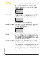
Error
Cause
Rectification
Measured val
-
ue on the display
and adjustment
module does not
correspond to the
value in the PLC
The menu item
"
Display - Display
value
" is not set to
"
PA-Out
"
Check values and correct, if neces
-
sary
No connection be
-
tween PLC and
PA network
Incorrect adjust
-
ment of the bus
parameter and the
segment coupler-
dependent baud
rate
Check data and correct, if necessary
Instrument does
not appear during
connection setup
Profibus DP cable
pole-reversed
Check cable and correct, if necessary
Incorrect termi-
nation
Check termination at the beginning
and end points of the bus and termi
-
nate, if necessary, according to the
specification
Instrument not
connected to the
segment, double
assignment of an
address
Check and correct, if necessary
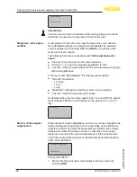
In Ex applications, the regulations for the wiring of intrinsically safe
circuits must be observed.
Error
Cause
Rectification
E013
no measured val
-
ue available
Sensor in boot phase
Sensor does not find an echo, e.g.
due to faulty installation or wrong pa
-
rameter adjustment
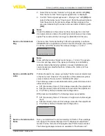
E017
Adjustment span
too small
Carry out a fresh adjustment and in
-
crease the distance between min. and
max. adjustment
E036
no operable sen
-
sor software
Carry out a software update or send
instrument for repair
E041
Hardware error,
electronics de
-
fective
Exchange the instrument or send it in
for repair
E113
Communication
conflict
Exchange the instrument or send it in
for repair
Depending on the reason for the fault and the measures taken, the
steps described in chapter "
Set up
" may have to be carried out again.
8.3 Exchanging the electronics module
If the electronics module is defective, it can be replaced by the user.
In Ex applications, only instruments and electronics modules with ap
-
propriate Ex approval may be used.
Error messages via the
display and adjustment
module
Reaction after fault recti-
fication


