


29
6 Set up with the display and adjustment module PLICSCOM
VEGASON 62 • Profibus PA
28785-EN-150603
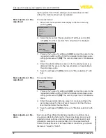
Approx. 60 minutes after the last pressing of a key, an automatic reset
to measured value indication is triggered. Any values not confirmed
with
[OK]
will not be saved.
6.3 Setup steps
Before starting the actual parameter adjustment of a Profibus PA
sensor, the address setting must first be carried out. You will find a
detailed description in the operating instructions manual of the display
and adjustment module or in the online help of PACTware or DTM.
Level and pressure sensors operate as slaves on the Profibus PA. To
be identified as a bus participant, each sensor must have a unique
address. Each instrument is delivered with address 126. With this
address, it can at first be connected to an existing bus. However, the
address must be changed. This can be done in this menu item.
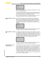
Sensor address
126
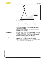
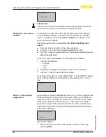
The sensor measures the distance from the sensor to the product
surface. For indication of the real level, an allocation of the measured
distance to the percentage height must be carried out.
The actual level is then calculated on the basis of these entered
values. At the same time, the operating range of the sensor is limited
from maximum range to the requested range.
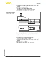
100%
0%
0,5 m (19.68
")
5 m
(196.9
")
2
1
3
Fig. 28: Parameter adjustment example min./max. adjustment
1 Min. level = max. measuring distance
2 Max. level = min. measuring distance
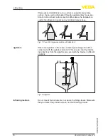
The real product level during this adjustment is not important, be
-
cause the min./max. adjustment is always carried out without chang
-
Address setting
Basic adjustment - Sen-
sor address
Parameter adjustment


