BeamMonitor BM+
35,0(6
33
Revision 02/2019 EN
16.2
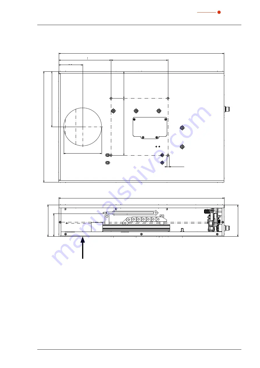
BeamMonitor BM+ 100
Beam
436
150
138
63
Ø 100
4x M6
292
146
71
83
60,25
Laser beam
All dimensions in mm (general tolerance ISO 2768-v)
Page 1: ...BeamMonitor BM BM 60 BM 100 LaserDiagnosticsSoftware LDS 35 0 6 Revision 02 2019 EN Operating Manual Translation of the original instructions ...
Page 2: ......
Page 3: ...BeamMonitor BM 35 0 6 3 Revision 02 2019 EN IMPORTANT READ CAREFULLY BEFORE USE KEEP FOR FUTURE USE ...
Page 4: ...wer supply 19 8 2 2 PRIMES bus RS485 19 8 3 Connection to the PC and establishing the power supply 20 8 4 Connection of the BeamMonitor BM and PowerMonitor PM 48 100 to the PC 21 9 Status display 22 10 Measuring 23 10 1 Safety instructions 23 10 2 Connect the BeamMonitor BM with the LaserDiagnosticsSoftware LDS 24 10 2 1 Connect device 24 10 2 2 Change the network address of a connected device 24 ...
Page 5: ...ons 32 16 1 BeamMonitor BM 60 32 16 2 BeamMonitor BM 100 33 17 Appendix 34 17 1 System control option 34 17 2 Variety of detectors 34 17 3 Replace the detector 35 17 3 1 Remove cover 35 17 3 2 Disassemble the detector 35 17 3 3 Assemble the detector 37 17 3 4 Replace cover 37 ...
Page 6: ...suring devices to determine the following beam parameters Laser power Beam dimensions and position of an unfocused beam Beam dimensions and position of a focused beam Beam quality factor M PRIMES is responsible for both the development production and calibration of the measuring devices This guarantees optimum quality excellent service and a short reaction time providing the basis for us to meet a...
Page 7: ...ulletin published by the Laser Institute of America as well as the Guide of Control of Laser Hazards by ACGIH Necessary safety measures DANGER Serious eye or skin injury due to laser radiation Depending on the measuring principle used the laser beam is reflected at the measuring tip laser class 4 The reflected beam is usually not visible X In measurement mode a safety distance of one meter to the ...
Page 8: ...afety related without our explicit permission The device must not be opened e g to carry out unauthorized repairs Modifications of any kind will result in the exclusion of our liability for resulting damages Liability disclaimer The manufacturer and the distributor of the measuring devices do not claim liability for damages or injuries of any kind resulting from an improper use or handling of the ...
Page 9: ...ical injury may occur if necessary safety precautions are not taken NOTICE Means that property damage may occur if necessary safety precautions are not taken The following symbols indicating requirements and possible dangers are used on the device Hand injuries warning Read and observe the operating instructions and safety guidelines before startup Further symbols that are not safety related Here ...
Page 10: ...er to the separate operating manual LaserDiagnosticsSoftware LDS 4 Conditions at the installation site The device must not be operated in a condensing atmosphere The ambient air must be free of organic gases Protect the device from splashes of water and dust Operate the device in closed rooms only DANGER Fire and explosion hazards due to scattered or directed laser radiation When the BeamMonitor B...
Page 11: ...gh power laser beam of CO2 or NIR lasers A rotating measuring tip scans the laser beam along the x axis During this process the very small mirror in the measuring tip separates out a small part of the radiation The horizontal carrier moves the measuring tip along the y axis in order to measure the beam properties of the laser beam on the x y plane Another mirror finally guides the measurement sign...
Page 12: ...ecautions Chapter 1 on page 7 3 Prepare Installation Observe safety instructions Make preparations Set installation position Chapter 7 on page 13 4 Electrical connection Establish voltage supply Chapter 8 on page 18 5 Connect with the computer Via Ethernet or LAN Chapter 8 3 on page 20 6 Connect with the PowerMonitor PM 48 100 Via RS485 Chapter 8 4 on page 21 7 Perform the measurement Observe safe...
Page 13: ...device in the original PRIMES transport box 7 Installation 7 1 Safety instructions Areas on the device that could be particularly hazardous for hand injuries are marked with the following pic togram Hand injuries warning CAUTION Risk of injury caused by rotating parts The measuring tip of the BeamMonitor BM rotates at high speed during the measuring operation X Do not reach into or hold any object...
Page 14: ...e bricks or other partly absorbing surfaces are not suitable X Use an adequate absorber Dependent on the application PRIMES offers suitable absorbers such as the PowerMonitor PM 48 100 X Don t store any flammable materials or highly flammable substances at the measuring loca tion 7 3 Installation position The BeamMonitor BM can also be mounted horizontally or vertically Beam incidence Mounting sur...
Page 15: ...f radii according to the second moment method measuring errors are otherwise possible 7 5 Install the BeamMonitor BM DANGER Serious eye or skin injury due to laser radiation If the device is moved from its calibrated position increased scattered or directed reflection of the laser beam occurs during measuring operation laser class 4 X Mount the device so that it cannot be moved by an unintentional...
Page 16: ...BeamMonitor BM 35 0 6 16 Revision 02 2019 EN 7 5 1 Install the BeamMonitor BM 60 Beam M6 M6 M6 M6 Fig 7 3 Mounting holes on the BeamMonitor BM 60 ...
Page 17: ...BeamMonitor BM 35 0 6 17 Revision 02 2019 EN 7 5 2 Install the BeamMonitor BM 100 Beam M6 M6 M6 M6 Fig 7 4 Mounting holes on the BeamMonitor BM 100 ...
Page 18: ...48 100 is transmitted through the BeamMonitor BM to the PC via the Ethernet interface The additional measuring device is powered by the power supply of the BeamMonitor BM Please use only the provided PRIMES power supply and connection lines Please ensure that all electrical connections have been established and switch the device on before starting the LaserDiagnosticsSoftware LDS The BeamMonitor B...
Page 19: ...Function 1 24 V 2 Not assigned 3 GND 4 Not assigned 5 FE functional earth Tab 8 1 Connection socket for the power supply 8 2 2 PRIMES bus RS485 Pin arrangement D sub socket 9 pin view of plug in side 1 5 6 9 Pin Function 1 GND 2 RS485 3 24 V 4 Not assigned 5 Not assigned 6 GND 7 RS485 8 24 V 9 Not assigned Tab 8 2 D sub socket PRIMES bus ...
Page 20: ...e power supply Ethernet LAN or Patch cable LMax 1 8 m PRIMES power supply BeamMonitor BM LMax 2 0 m Crossover cable Ethernet PC Fig 8 2 Connection of BeamMonitor BM using the example of the BM 100 Connect the BeamMonitor BM to the PC via a crossover cable or to the network via a patch cable ...
Page 21: ... m PRIMES power supply LMax 2 0 m LMax 10 m Crossover cable PRIMES bus RS485 Ethernet PC Fig 8 3 Connection of the BeamMonitor BM using the example of the BM 100 and PowerMonitor PM 48 100 to the PC NOTICE Damage Destruction of the device due to overvoltage When disconnecting the electric cables during operation when the supply voltage is con nected voltage peaks can be generated that could destro...
Page 22: ...BeamMonitor BM with differ ent colors and static or rotating lights Color Lighting state Meaning White The entire ring illuminates The supply voltage is connected Yellow Rotating light The measuring tip rotates Red Rotating light The measuring tip rotates and the y axis is moved The measurement is in progress Tab 9 1 States of the status display ...
Page 23: ...diation If the device is moved from its calibrated position increased scattered or directed reflection of the laser beam occurs during measuring operation laser class 4 X Mount the device so that it cannot be moved by an unintentional knock or cables being pulled accidentally DANGER Fire and explosion hazards due to scattered or directed laser radiation When the BeamMonitor BM is being operated th...
Page 24: ...s tab 4 Click on the Connect to device button under the tab The Connections window appears 5 Click on the desired device 6 Click on the Connect to device but ton 10 2 2 Change the network address of a connected device Proceed as follows in order to assign a dif ferent IP address to a connected device 1 Right click on the device and select the Device settings menu point 2 Enter in the desired IP ad...
Page 25: ...separate operating manual LaserDiagnosticsSoftware LDS 10 3 1 Selecting the measuring mode single planes 1 Connect the device according to chapter 10 2 on page 24 with the LaserDiagnosticsSoftware LDS TheBeamMonitor BM is established as a connected device 2 Click on the Scanner function The Device control menu opens 3 Click on the Measuring mode drop down list 4 Click on the entry Single planes Me...
Page 26: ...ding to chapter 10 3 4 on page 28 The beam is displayed in the mea surement window If the beam can not be displayed in crease the laser power and or adjust the gain Automatic beam search When activating the checkbox autom Measuring window the laser beam is searched automatically and an optimally adjusted measuring window is placed around the beam 1 Mark the checkbox autom Mea surement window 2 Sta...
Page 27: ...ocal length option The input of the laser power and focal length is needed for the calculation of the beam quality factor M the power density and the raw beam diameter etc 5 Enter the laser Power P in W 6 For a built in focusing optics enter the Focal length of focusing optic in mm Averaging By placing a check mark next to Averag ing you can select various algorithms for averaging the measuring va...
Page 28: ...ed with the optimal measurement parameters Measurement completed The measurement has been completed 4 Turn off the laser 5 Click on the Stop Rotation button to turn off the measurement tip rotation Averaging The information shows measured planes analyzed in order to average a measuring value 10 3 5 Measurement results display The measurement results are shown in the opened tools after the measurem...
Page 29: ...n the Pixel in x y section to something like 1 024 x 1 024 pixels The signal enhancement is too low Enter the maximum value of 0 dB in the dialog window Device control Single plane Settings in the Gain in db section Tab 11 1 Troubleshooting 12 Maintenance and service The operator is responsible for determining the maintenance intervals for the measuring device PRIMES recommends a maintenance inter...
Page 30: ...BeamMonitor BM 35 0 6 30 Revision 02 2019 EN 14 Declaration of conformity ...
Page 31: ...ange x y 60 x 60 mm 100 x 100 mm Measurement window sizes 0 1 x 0 1 60 x 60 mm 0 1 x 0 1 100 x 100 mm Resolution 32 x 32 1024 x 1024 Pixel Rotation speed of the measuring tip 1 562 rpm Accuracy beam diameter 5 Reproducibility beam diameter 3 Supply data Power supply 24 V DC 5 max 1 8 A Communication Interfaces RS485 Ethernet Dimensions and weight BM 60 BM 100 Dimensions LxWxH 316 x 212 x 83 mm 436...
Page 32: ...BeamMonitor BM 35 0 6 32 Revision 02 2019 EN 16 Dimensions 16 1 BeamMonitor BM 60 Laser beam 316 83 60 25 Beam 4x M6 76 60 316 133 60 43 212 106 Ø 60 All dimensions in mm general tolerance ISO 2768 v ...
Page 33: ...BeamMonitor BM 35 0 6 33 Revision 02 2019 EN 16 2 BeamMonitor BM 100 Beam 436 150 138 63 Ø 100 4x M6 292 146 150 71 Beam 83 83 60 25 Laser beam 436 All dimensions in mm general tolerance ISO 2768 v ...
Page 34: ...ions 17 2 Variety of detectors Different detectors are used depending on the application see Tab 17 1 on page 34 Detector type Laser Type of sensor Amplification Wavelength range in μm DBC CO2 Pyroelectric detector 1 9 12 DBY PS NIR VIS Photodiode Automatic adjustment of the sensitivity 0 4 1 1 DBIG PS NIR Photodiode Automatic adjustment of the sensitivity x 0 9 1 7 Tab 17 1 Variety of detectors ...
Page 35: ...screw four torx screws T8 from the cover 3 Lift the cover to remove it Under the cover is the detector Torx T8 Torx T8 Torx T8 Torx T8 Fig 17 1 Opened cover of BeamMonitor BM with detector 17 3 2 Disassemble the detector NOTICE Damage of the detector Touching the sensor surface will damage the detector This can negatively affect the measur ing results X Do not touch the detector with your fingers ...
Page 36: ...D D Fig 17 3 Remove the plastic screws from the detector 2 Carefully remove the detector from the position X X Please do not pull the cables 3 First loosen the golden angle plug A then the black plug B see Fig 17 4 on page 36 A B Do not compress here Touch here Touch here Fig 17 4 Releasing the plugs from the detector ...
Page 37: ... on the mounting surface of the detector see Fig 17 5 on page 37 2 Connect the cables NOTICE Blocking the rotational disc If the screws are tightened too firmly they might block the rotational disc X Only tighten the screws hand tight The foam rubber spacer must only be compressed to no more than half its original thickness 3 Fasten the detector with the two plastic screws D C D Fig 17 5 Assemblin...
Page 38: ...BeamMonitor BM 35 0 6 38 Revision 02 2019 EN ...