25
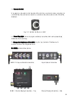
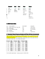
C. MDR3 Camera Cables
p/n Camera Model
Description
Connector
4721 Alexa, Arri 435/535, Sony F65
R/S
3 pin Fischer
4722
All
Panaflex
R/S
10-pin
Lemo
4730 Sony, Panasonic, Viper
VTR
12-pin Hirose
4746
RED
Epic R/S
BNC
4755
Sony
F5/F55
R/S
4-pin
hirose
D.
Transmitter Channel frequency allocation
and Power
(G4 blue dot transceivers)
Blue dot designated units can access 30 additional channels 30-59 with advanced coding.
These channels share the same frequencies as channels 0 – 29. (Channel 30 is the same
frequency as Channel 0). The advanced data coding allows units to be operated at close
proximity to other units (<1m) without interference.
Channel MHz Channel MHz
Channel
MHz
0 2402
10 2424
20 2458
1 2404
11 2428
21 2460
2 2406
12 2432
22 2462
3 2408
13 2436
23 2464
4 2410
14 2440
24 2466
5 2412
15 2444
25 2468
6 2414
16 2448
26 2470
7 2416
17 2452
27 2472
8 2418
18 2454
28 2474
9 2420
19 2456
29 2476
The maximum peak power / average power is 0.10W/0.01W.
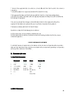
Command Serial Power Motor
Camera
6-pin
4-pin 2-pin
7-pin
10-pin
1 GND
+12V Batt(-)
Motor(+)
Batt(-)
2 24V
0.2A
Gnd
Batt(+)
Motor(-)
Serial
3
Serial 1
Serial In
Encoder A
Serial
4 Serial1
Serial
Out
+5V
Batt(+)
5 n/c
Gnd
Camera
R/S
6 n/c
Encoder B
Common R/S
7
Motor
ID
DSR
8
DTR
9
Camera
ID
10
Camera ID rtn

