1-4
Alarm Cards
Model No.
Running Head
Alarm Card Descriptions
Alarm Cards
1.2.3
ALR 28+14 Card Description (8403)
The ALR 28+14 Card has 28 sensors for incoming external alarms. Each sensor controls its
own alarm. The card also uses 14 switches to control external devices, and provides a single
FXS voice port.
The sensors allow you to connect up to 28 external devices to the card. These sensors may be
powered either externally or from the alarm card. They are divided into two groups, with 14
sensors per group. Each sensor group is routed through one of two Amphenol jacks, and you
can control the voltage to each group by operating a voltage control switch on the alarm card.
Detailed instructions for sensor control are provided later in this chapter.
The switches allow the card to control up to 14 external devices. As with the sensors, the
switches are divided between the two Amphenol connectors into two groups of seven switches
each. Twelve of the switches are Form C (open or closed based on user input), one is Form A
(always open), and one is Form B (always closed). One of the switches can also be set to trip
if a system power failure occurs. Instructions for switch control are provided later in this
chapter.
The alarm information can also be transmitted to a central site via SNMP or other user-defined
parameters.
1.2.3.1
Card Jumpers/Switch Settings
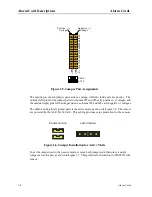
The ALR 28+14 Card has numerous jumper and other settings, as shown in Figure 1-3. These
settings are discussed in the following paragraphs.
Summary of Contents for ALR 28+14
Page 1: ...Alarm Cards Reference Guide Publication 999 001967 Revision A1 Release 3 9 October 1999 ...
Page 4: ...Model No Running Head ...
Page 6: ...ii Alarm Cards Model No Running Head Contents ...
Page 8: ...iv Alarm Cards Model No Running Head Figures ...
Page 10: ...vi Alarm Cards Model No Running Head Tables ...
Page 34: ...1 24 Alarm Cards Model No Running Head Alarm Card Troubleshooting Alarm Cards ...

