Alarm Cards
1-17
Alarm Cards
Alarm Card User Screens and Settings
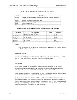
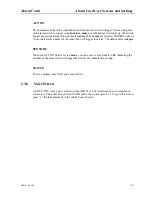
ACT ON
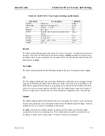
This parameter defines the condition that will cause the switch to trigger. You can program
each alarm switch to trigger on info, minor, major, or crit alarms. Alternatively, the switch
trigger can also be assigned to a particular sensor. When sensor is selected, SENSOR # allows
you to indicate the number of the sensor that will trigger the alarm. The default value is major.
SENSOR #
When the ACT ON field is set to sensor, you can enter a value from 1 to 28, indicating the
number of the sensor that will trigger the switch. The default value is n/a.
STATUS
This is a display-only field; you cannot edit it.
1.3.6
Voice Screen
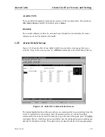
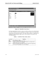
An RJ-11 FXS voice port is located on the ALR 28+14 Card between the two Amphenol
connectors. The initial Voice Screen for this port is shown in Figure 1-12. To go to this screen,
press “v” (Voice command) in the Alarm Sensor Screen.
Summary of Contents for ALR 28+14
Page 1: ...Alarm Cards Reference Guide Publication 999 001967 Revision A1 Release 3 9 October 1999 ...
Page 4: ...Model No Running Head ...
Page 6: ...ii Alarm Cards Model No Running Head Contents ...
Page 8: ...iv Alarm Cards Model No Running Head Figures ...
Page 10: ...vi Alarm Cards Model No Running Head Tables ...
Page 34: ...1 24 Alarm Cards Model No Running Head Alarm Card Troubleshooting Alarm Cards ...

