Replacement Procedure
Review entire procedure before starting.
Removal Instructions
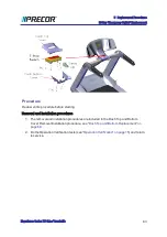
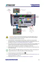
1. Switch the power OFF and
unplug
1
the power cord.
2. Remove the hood cover, see
"Hood Cover Replacement" on page 56
3. Facing the front of the treadmill, remove the two right side 5/16" hex fasteners and then
loosen the two left side 5/16" hex fasteners (approx, 4 full turns). Slide the MC base to
the right to remove. Retain fastener hardware for installation.
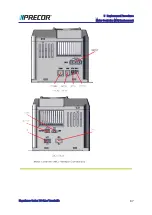
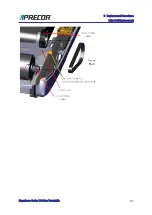
4. Carefully raise front and rear of MC as needed to disconnect the attached
I/O
2
interface
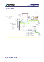
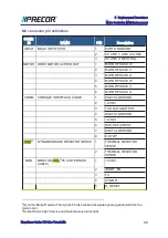
cable connectors, see .
"Motor Controller (MC) Replacement" on page 84
.
Note
: The COMM connector contacts have an application of dielectric grease
to ensure proper electrical contact. Do not wipe off, clean, or remove the dielec-
tric grease.
Installation Instructions
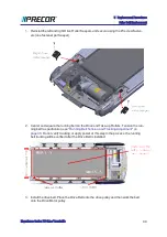
1. Place the MC into the drive motor compartment and reconnect the removed MC I/O
cable connectors. It will be easier to attach the connectors before installing the MC into
1
Disconnect a device power cord plug or cable connector from the power receptacle or outlet.
2
Input and Output Interface.
Experience Series 700 Line Treadmills
92
5 Replacement Procedures
Motor Controller (MC) Replacement
Summary of Contents for Experience TRM700-16
Page 1: ...Service Manual Experience Series 700 line TRM700 16 Base Treadmill 120 VAC and 240 VAC ...
Page 19: ...Experience Series 700 Line Treadmills 12 1 Introduction General Information ...
Page 104: ...Experience Series 700 Line Treadmills 97 5 Replacement Procedures Drive Belt Replacement ...
Page 172: ...Experience Series 700 Line Treadmills 165 8 Theory of Operation System Wiring Diagram ...
Page 174: ...Experience Series 700 Line Treadmills 167 8 Theory of Operation Exploded View Diagram ...
Page 175: ...Experience Series 700 Line Treadmills 168 8 Theory of Operation Exploded View Diagram ...
Page 176: ...Experience Series 700 Line Treadmills 169 8 Theory of Operation Exploded View Diagram ...
Page 177: ...Experience Series 700 Line Treadmills 170 8 Theory of Operation Exploded View Diagram ...
Page 178: ...Experience Series 700 Line Treadmills 171 8 Theory of Operation Exploded View Diagram ...
Page 179: ...Experience Series 700 Line Treadmills 172 8 Theory of Operation Exploded View Diagram ...
Page 181: ...Experience Series 700 Line Treadmills 174 8 Theory of Operation Parts List ...
Page 182: ...Experience Series 700 Line Treadmills 175 8 Theory of Operation Parts List ...
Page 183: ...Experience Series 700 Line Treadmills 176 8 Theory of Operation Parts List ...

