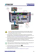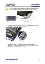
CAUTION
: Take your time and be careful when reconnecting the MC cable con-
nectors. Many of the connector contacts are small and can be easily damaged if
incorrectly inserted into the MC connector.
4. Reinstall the MC by sliding the left side base flange under the two left preinstalled
loosened fasteners. Then install the two right side fasteners and fully tighten all four 1/2"
hex fasteners, see
"Motor Controller (MC) Replacement" on page 84
5. Route cables and secure using the three frame cable clamps. Recheck all cable MC con-
nections and make sure that the cables have freedom of movement and clear of any
frame or component edges that could pinch or damage the cable wires.
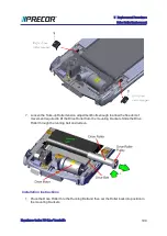
6. Reinstall the drive belt. Place the Drive Belt onto the Roller pulley and walk the belt onto
the Drive Motor pulley.
TIP
: Use (turn) the Drive Motor flywheel to make it easier to turn the motor pulley and
help walk the belt onto or off the Drive Motor and Drive Roller pulleys.
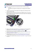
7. Connect the power cord and switch the power ON.
8. Verify the Drive Belt alignment and tension to specification. see
Alignment Adjustment" on page 36
.
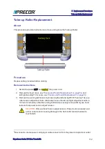
9. Reinstall the hood cover, see
"Hood Cover Replacement" on page 56
.
Experience Series 700 Line Treadmills
105
5 Replacement Procedures
Drive Motor Replacement
Summary of Contents for Experience TRM700-16
Page 1: ...Service Manual Experience Series 700 line TRM700 16 Base Treadmill 120 VAC and 240 VAC ...
Page 19: ...Experience Series 700 Line Treadmills 12 1 Introduction General Information ...
Page 104: ...Experience Series 700 Line Treadmills 97 5 Replacement Procedures Drive Belt Replacement ...
Page 172: ...Experience Series 700 Line Treadmills 165 8 Theory of Operation System Wiring Diagram ...
Page 174: ...Experience Series 700 Line Treadmills 167 8 Theory of Operation Exploded View Diagram ...
Page 175: ...Experience Series 700 Line Treadmills 168 8 Theory of Operation Exploded View Diagram ...
Page 176: ...Experience Series 700 Line Treadmills 169 8 Theory of Operation Exploded View Diagram ...
Page 177: ...Experience Series 700 Line Treadmills 170 8 Theory of Operation Exploded View Diagram ...
Page 178: ...Experience Series 700 Line Treadmills 171 8 Theory of Operation Exploded View Diagram ...
Page 179: ...Experience Series 700 Line Treadmills 172 8 Theory of Operation Exploded View Diagram ...
Page 181: ...Experience Series 700 Line Treadmills 174 8 Theory of Operation Parts List ...
Page 182: ...Experience Series 700 Line Treadmills 175 8 Theory of Operation Parts List ...
Page 183: ...Experience Series 700 Line Treadmills 176 8 Theory of Operation Parts List ...

