Side Arm Upper/Lower Covers Replacement
Side Arm Upper/Lower Covers Replacement
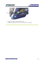
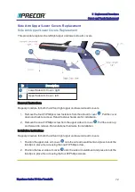
This procedure replaces the left/right upper and lower side arm covers.
ID
Description
Lower Side Arm Cover - right
Upper Side Arm Cover - left
Removal Instructions
Repeat procedure for both the left and right upper and lower side arm covers.
1. Remove the four #3 Phillips screw fasteners from the side arm cover
. Pull the cover
down and back to remove. Retain fastener hardware for installation.
2. Remove the one #3 Phillips screw from the upper side arm cover
. Pull the cover up
and forward to remove. Retain fastener hardware for installation.
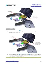
Installation Instructions
Repeat procedure for both the left and right upper and lower side arm covers.
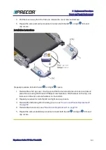
1. Position the upper side arm cover
onto the side arm weldment and press to lock the
tab clips in place. Secure using the one #3 Phillips screw,
2. Position the lower side arm cover
onto the side arm weldment and press to lock the
tab clips in place. Secure using the four #3 Phillips screws.
Experience Series 700 Line Treadmills
72
5 Replacement Procedures
Covers and Panels Replacement
Summary of Contents for Experience TRM700-16
Page 1: ...Service Manual Experience Series 700 line TRM700 16 Base Treadmill 120 VAC and 240 VAC ...
Page 19: ...Experience Series 700 Line Treadmills 12 1 Introduction General Information ...
Page 104: ...Experience Series 700 Line Treadmills 97 5 Replacement Procedures Drive Belt Replacement ...
Page 172: ...Experience Series 700 Line Treadmills 165 8 Theory of Operation System Wiring Diagram ...
Page 174: ...Experience Series 700 Line Treadmills 167 8 Theory of Operation Exploded View Diagram ...
Page 175: ...Experience Series 700 Line Treadmills 168 8 Theory of Operation Exploded View Diagram ...
Page 176: ...Experience Series 700 Line Treadmills 169 8 Theory of Operation Exploded View Diagram ...
Page 177: ...Experience Series 700 Line Treadmills 170 8 Theory of Operation Exploded View Diagram ...
Page 178: ...Experience Series 700 Line Treadmills 171 8 Theory of Operation Exploded View Diagram ...
Page 179: ...Experience Series 700 Line Treadmills 172 8 Theory of Operation Exploded View Diagram ...
Page 181: ...Experience Series 700 Line Treadmills 174 8 Theory of Operation Parts List ...
Page 182: ...Experience Series 700 Line Treadmills 175 8 Theory of Operation Parts List ...
Page 183: ...Experience Series 700 Line Treadmills 176 8 Theory of Operation Parts List ...

