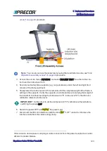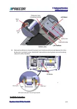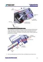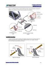
2. Place the extension tube into the lift platform mounting bracket and secure using the
hitch pin and clevis pin. It may be necessary to slightly rotate the extension tube to align
the clevis pin mounting holes. If the extension tube has been rotated during or after it
was removed, recalibrate the lift motor prior to installation, see
Remove supports and lower the treadmill
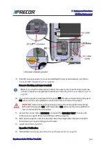
1. Connect the power cord and switch the power ON. Be aware that switching the power
ON will cause the incline platform to move and return to the level "0" position. If you are
using the side access method, see
"Side lift platform assembly access" on page 49
to
upright the treadmill.
WARNING
: Keep hands and appendages clear of the incline platform
assembly before switching power ON. Switching power ON will cause the
incline platform to move to the level "0" Home position.
2. Access the service menu (51765761) and select the INCLINE TEST. Increase the
incline level enough to lift the treadmill frame off the supports.
3. Remove the supports and clear any other items that might either block the treadmill
from lowering or may be damaged as it lowers.
4. Lower the incline to level "0".
Operation Verification
5. Verify the treadmill incline operation from minimum to maximum levels.Make sure that
there are no active Incline function related error codes.
Experience Series 700 Line Treadmills
135
5 Replacement Procedures
Lift Platform Replacement
Summary of Contents for Experience TRM700-16
Page 1: ...Service Manual Experience Series 700 line TRM700 16 Base Treadmill 120 VAC and 240 VAC ...
Page 19: ...Experience Series 700 Line Treadmills 12 1 Introduction General Information ...
Page 104: ...Experience Series 700 Line Treadmills 97 5 Replacement Procedures Drive Belt Replacement ...
Page 172: ...Experience Series 700 Line Treadmills 165 8 Theory of Operation System Wiring Diagram ...
Page 174: ...Experience Series 700 Line Treadmills 167 8 Theory of Operation Exploded View Diagram ...
Page 175: ...Experience Series 700 Line Treadmills 168 8 Theory of Operation Exploded View Diagram ...
Page 176: ...Experience Series 700 Line Treadmills 169 8 Theory of Operation Exploded View Diagram ...
Page 177: ...Experience Series 700 Line Treadmills 170 8 Theory of Operation Exploded View Diagram ...
Page 178: ...Experience Series 700 Line Treadmills 171 8 Theory of Operation Exploded View Diagram ...
Page 179: ...Experience Series 700 Line Treadmills 172 8 Theory of Operation Exploded View Diagram ...
Page 181: ...Experience Series 700 Line Treadmills 174 8 Theory of Operation Parts List ...
Page 182: ...Experience Series 700 Line Treadmills 175 8 Theory of Operation Parts List ...
Page 183: ...Experience Series 700 Line Treadmills 176 8 Theory of Operation Parts List ...


