Lift motor calibration
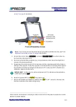
1. Lay the replacement lift motor on the floor in front of the treadmill. Connect the the lift
motor interface cable to the MC "LIFT" connector.
2. Connect the power cord and switch the power from OFF to ON. This will set the lift
motor to the calibration reference incline level "0".
3. Switch the power OFF and unplug the power cord.
4. Disconnect the MC "LIFT' connection.
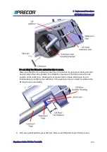
5. Firmly hold the jackscrew and rotate the extension tube to adjust the calibration dis-
tance. The calibration distance is measured between the top of the extension tube nut
and the lift motor actuator housing. Adjust the calibration distance to specification
between 1 1/8 in - 1 3/16 in (2.8 cm - 3.0 cm).
IMPORTANT
: Make sure the extension tube does not rotate after setting the cal-
ibration distance. Use tape to mark the extension tube position on the jackscrew.
Lift motor installation
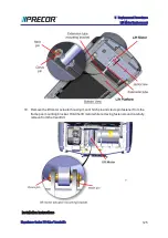
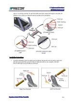
6. Clean and apply a thin layer of synthetic grease to the inside of the lift motor actuator
housing clevis pin mounting hole . Then install the pre-calibrated lift motor placing the
treadmill actuator housing mount into the frame pan mounting bracket. Secure using the
clevis pin and hitch pin.
Experience Series 700 Line Treadmills
126
5 Replacement Procedures
Lift Motor Replacement
Summary of Contents for Experience TRM700-16
Page 1: ...Service Manual Experience Series 700 line TRM700 16 Base Treadmill 120 VAC and 240 VAC ...
Page 19: ...Experience Series 700 Line Treadmills 12 1 Introduction General Information ...
Page 104: ...Experience Series 700 Line Treadmills 97 5 Replacement Procedures Drive Belt Replacement ...
Page 172: ...Experience Series 700 Line Treadmills 165 8 Theory of Operation System Wiring Diagram ...
Page 174: ...Experience Series 700 Line Treadmills 167 8 Theory of Operation Exploded View Diagram ...
Page 175: ...Experience Series 700 Line Treadmills 168 8 Theory of Operation Exploded View Diagram ...
Page 176: ...Experience Series 700 Line Treadmills 169 8 Theory of Operation Exploded View Diagram ...
Page 177: ...Experience Series 700 Line Treadmills 170 8 Theory of Operation Exploded View Diagram ...
Page 178: ...Experience Series 700 Line Treadmills 171 8 Theory of Operation Exploded View Diagram ...
Page 179: ...Experience Series 700 Line Treadmills 172 8 Theory of Operation Exploded View Diagram ...
Page 181: ...Experience Series 700 Line Treadmills 174 8 Theory of Operation Parts List ...
Page 182: ...Experience Series 700 Line Treadmills 175 8 Theory of Operation Parts List ...
Page 183: ...Experience Series 700 Line Treadmills 176 8 Theory of Operation Parts List ...

