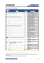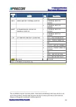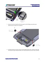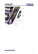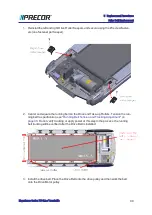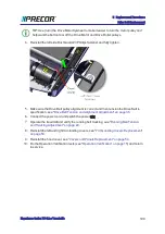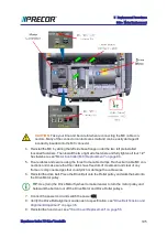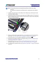
3. Disconnect the Motor Controller "MTH" and "MOTOR" electrical connections:
a. Remove the
MC
1
base from the mounting fasteners to allow connector access,
see
"Motor Controller (MC) Replacement" on page 84
.
b. Disconnect the MC "MTH" and "MOTOR" interface cable connectors, see
Controller (MC) Replacement" on page 84
.
c. Remove the motor interface cable from the three frame cable clamps.
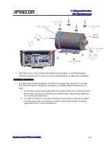
4. Use a 5/16" socket (or nut driver) to remove the Drive Motor static bleed resistor ground
wire (Orange wire). Retain fastener hardware for installation.
5. Use tape or marker to make a motor base position reference mark. This reference mark
will be used to help position the replacement motor installation position.
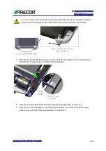
6. Remove Drive Belt tension by loosening the four Drive Motor
1/2" hex head fasten-
ers. Remove the Drive Belt by walking the belt off the Roller pulley and then the motor
pulley.
1
Motor Controller Module
Experience Series 700 Line Treadmills
102
5 Replacement Procedures
Drive Motor Replacement
Summary of Contents for Experience TRM700-16
Page 1: ...Service Manual Experience Series 700 line TRM700 16 Base Treadmill 120 VAC and 240 VAC ...
Page 19: ...Experience Series 700 Line Treadmills 12 1 Introduction General Information ...
Page 104: ...Experience Series 700 Line Treadmills 97 5 Replacement Procedures Drive Belt Replacement ...
Page 172: ...Experience Series 700 Line Treadmills 165 8 Theory of Operation System Wiring Diagram ...
Page 174: ...Experience Series 700 Line Treadmills 167 8 Theory of Operation Exploded View Diagram ...
Page 175: ...Experience Series 700 Line Treadmills 168 8 Theory of Operation Exploded View Diagram ...
Page 176: ...Experience Series 700 Line Treadmills 169 8 Theory of Operation Exploded View Diagram ...
Page 177: ...Experience Series 700 Line Treadmills 170 8 Theory of Operation Exploded View Diagram ...
Page 178: ...Experience Series 700 Line Treadmills 171 8 Theory of Operation Exploded View Diagram ...
Page 179: ...Experience Series 700 Line Treadmills 172 8 Theory of Operation Exploded View Diagram ...
Page 181: ...Experience Series 700 Line Treadmills 174 8 Theory of Operation Parts List ...
Page 182: ...Experience Series 700 Line Treadmills 175 8 Theory of Operation Parts List ...
Page 183: ...Experience Series 700 Line Treadmills 176 8 Theory of Operation Parts List ...

