PowerQuick Powered Ascender
(17)
PQ500-1 1-Sep-15
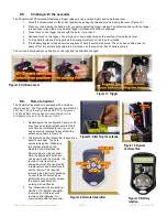
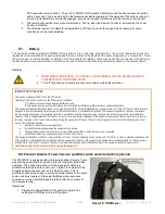
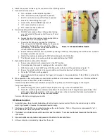
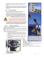
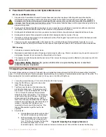
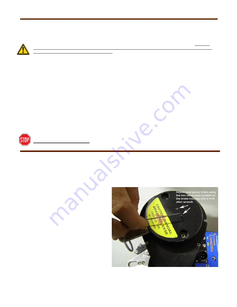
Figure 30: Adjusting the emergency brake lever
9.
PowerQuick Powered Ascender System Maintenance
9.1.
General
Maintenance
1. All parts of the PowerQuick Powered Personal Ascender and other equipment affecting safe operation shall be
maintained in proper working order so that they may perform the functions for which they were intended. Check for
misalignment or binding of moving parts, breakage of parts, and any other condition that may effect the operation. If
damaged, have the ascender serviced before using
.
The equipment shall be taken out of service when any part is not in
proper working order.
2. Employer shall demonstrate that all equipment is used, inspected and maintained in accordance with manufacture
r’s
instructions. Provisions shall be made for the retirement of equipment as necessary.
3. Employer shall establish and monitor a procedure to ensure all items of equipment are inspected before each use.
4. Employer shall ensure that equipment is protected from damage during the course of its use.
5.
If a defect is found during inspection the ascender should be “Red Tagged” to prevent its use until is has been serviced
by an Authorized Service Facility.
6. There are no user serviceable parts in this ascender. The unit should be sent to PowerQuick Concepts, Inc. or an
Authorized Service Facility for maintenance and repairs. Opening sealed parts of the PowerQuick voids all warranties.
9.2.
Cleaning
1. Controls and contacts shall be kept clean.
2. Maintenance specifically consists of cleaning all exterior parts with a rag. Water or cleansers may be used to remove dirt
and grease, however do not immerse the PowerQuick unit in liquid.
3. The capstan and all other parts shall be kept clean if their proper functioning would be affected by the presence of dirt or
other contaminants.
Inoperative Safety Devices.
No person shall render a required safety device or electrical
protective device inoperative.
10.
Adjusting the Manual Brake Lever
The manual brake release is a means of releasing the multi-plate disc brake allowing the PQ 500 to descend without electrical
power. For this brake release to function properly, adjustment may be necessary to accommodate normal wear of the parts. The
following adjustment should be performed weekly in heavy use or monthly with light use:
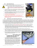
1. Locate the proper Allen key (1/16 inch) to fit the two #8-32 set screws.
2. Hang the PQ 500 on a rope with a load of at
least 100 pounds applied.
3. Test for proper tension on the brake lever by
pressing the brake lever. The brake lever will
move about ½ inch when depressed. The first
1/16 to 1/8 inch should have little resistance
followed by higher spring force. The first spring
is just a return spring for the lever, the second
stronger spring is the brake spring. (NOTE if
there is no free play, the brake may not engage,
if there is too much free play, the brake may not
release.) Adjusting this free play is very
important to the function of the machine. This
takes a little practice to get the feel for the
operation.
4. Adjustments:
a. All adjustments should be made so that
the two set screws are generally even.
b. With slight pressure on the brake lever,
loosen one of the set screws about ¼
turn. This should increase the free play
and allow the brake lever to move
downward slightly. Loosen the second set screw a similar amount; this will further increase the free play.
Summary of Contents for PQ 500-1
Page 46: ......
Page 48: ...NOTES...

