


POWER ELECTRONICS
SD700
COMMONLY USED CONFIGURATIONS
47
6.
6.1.
Pressure Group Control with 3 Auxiliary Pumps, Start and
Stop on Demand
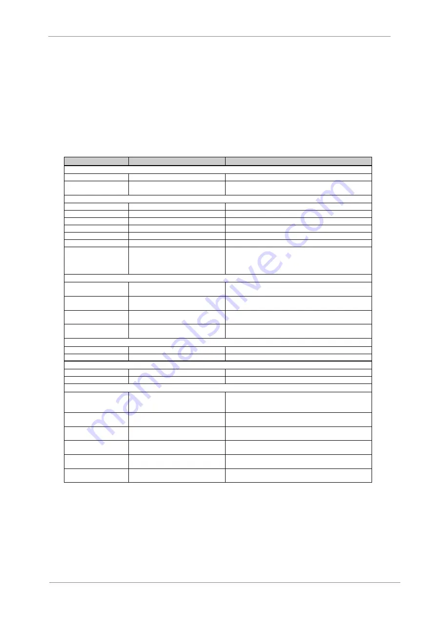
6.1.1.
Parameters Configuration
Parameter
Name / Description
Value
G1: Options Menu.
4 LANG=ENGLISH
G1.4
/ Language selection
ENGLISH
7 PROG = PUMP
G1.7
/ Program Activation
PUMP (It activates the extended functionality of the pump control in
group G25).
G2: Motor Nameplate.
1 MTR CURR=00.00A
G2.1
/ Motor rated current
__A (Set according to motor nameplate).
2 MTR VOLT=400V
G2.2
/ Motor rated voltage
__V (Set according to motor nameplate).
3 MTR PWR=00.0kW
G2.3
/ Motor rated power
__kW (Set according to motor nameplate).
4 MTR RPM=1485
G2.4
/ Motor rpm
__rpm (Set according to motor nameplate).
5 MTR PFA=0.85
G2.5
/ Cosine Phi
__ (Set according to motor nameplate).
6 MTR FRQ=50Hz
G2.6
/ Motor frequency
__Hz (Set according to motor nameplate).
7 MTR COOL=63%
G2.7
/ Motor cooling at zero speed
Use the following values as a reference:
Submersible pumps and non-deflagrating motors
5%
Self-cool motor
63%
Force-cooled motor
100%
G4: Inputs – S4.1: Digital Inputs.
5 DIGITL IN 1=50
G4.1.5
/ Multi-function Digital Input 1
configuration
50
PMP START/STP (Automatic starting of the system).
6 DIGITL IN 2=52
G4.1.6
/ Multi-function Digital Input 2
configuration
52
FIX PUMP1 FLT (Detection of auxiliary pump 1 in fault
status).
7 DIGITL IN 3=53
G4.1.7
/ Multi-function Digital Input 3
configuration
53
FIX PUMP2 FLT (Detection of auxiliary pump 2 in fault
status).
8 DIGITL IN 4=54
G4.1.8
/ Multi-function Digital Input 4
configuration
54
FIX PUMP3 FLT (Detection of auxiliary pump 3 in fault
status).
G25: Pump Control - S25.1: Setpoints.
1 CONTROL MODE=1
G25.1.1
/ Control mode
1
Pumps. The drive will start in pump control mode.
5 SETPT1=x.xBar
G25.1.5
/ Setpoint 1 for the PID
x.xBar
Local setpoint 1. (Set according to the installation).
G25: Pump Control - S25.2: PID Setting.
1 PID SETP=LOCAL
G25.2.1
/ PID reference source
LOCAL
Speed reference introduced by keypad.
3 PID FBK=AI2
G25.2.3
/ PID feedback source
AI2
Feedback signal connected to Analogue Input 2.
G25: Pump Control – S25.3: Start Conditions.
1 Lp Pon=0.0Bar
G25.3.1
/ Wake up level of the drive
x.xBar
When demand decreases, the drive can go in sleep
mode. (It allows setting the wake up level for the drive. This value is
set as units of PID setpoint).
2 FP SpON=90.0%
G25.3.2
/ Start speed for the fixed pumps
90.0%
It sets the drive speed above which fixed pumps will
start. (Set according to the installation).
3 FP ErON=10.0%
G25.3.3
/ Minimum PID error to start fixed
pumps
10.0%
This parameter allows user to consider the PID error (%)
at the moment of starting fixed pumps.
4 FP T1 ON=10.0s
G25.3.4
/ Delay time to start fixed pump 1 10.0s
It sets the delay time to start the fixed pump associated to
the relay 1.
5 FP T2 ON=10.0s
G25.3.5
/ Delay time to start fixed pump 2
10.0s
It sets the delay time to start the fixed pump associated to
the relay 2.
6 FP T3 ON=10.0s
G25.3.6
/ Delay time to start fixed pump 3 10.0s
It sets the delay time to start the fixed pump associated to
the relay 3.
Summary of Contents for SD700 Series
Page 1: ...Variable Speed Drive Application Manual PUMPS...
Page 2: ......
Page 3: ...Variable Speed Drive Application Manual PUMPS Edition March 2011 SD70MTAP01BI Rev B...
Page 4: ...SD700 POWER ELECTRONICS 2...
Page 8: ...SD700 POWER ELECTRONICS 6 INDEX...
Page 61: ......
Page 63: ...www power electronics com...