


POWER ELECTRONICS
SD700
DESCRIPTION OF PROGRAMMING PARAMETERS
35
Parameter
Name /
Description
Range
Function
Set on
RUN
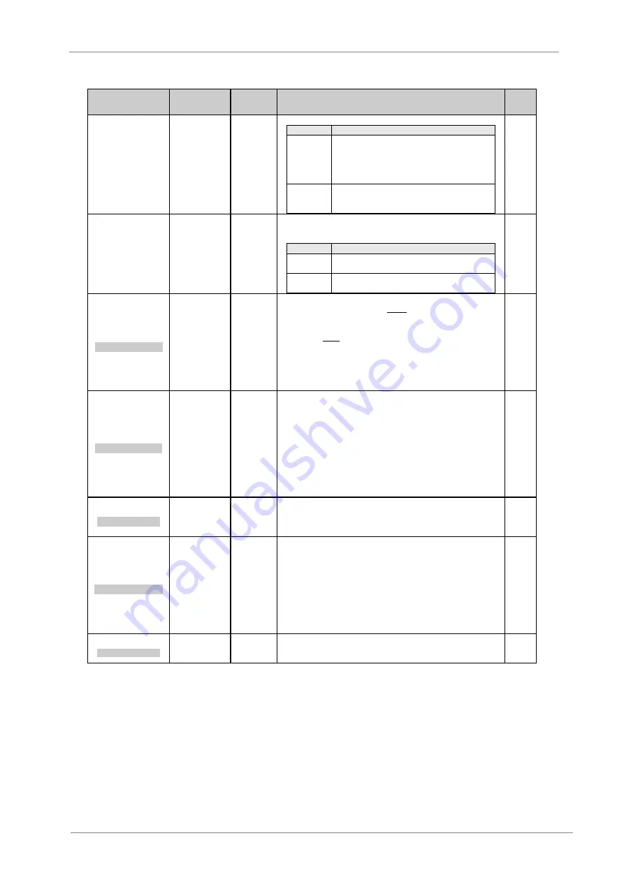
15 FLO SWm=PAUSE
G25.6.15
/
Response from No
Flow situation
PAUSE
FAULT
It allows selecting the drive response from No Flow detection situation.
OPT.
FUNCTION
PAUSE
It will generate the stopping of the drive, and next,
the fixed pumps. „NO FLOW‟ will be visualized.
Once the no flow condition disappears, if the
delay time after pause has elapsed, the drive will
start.
FAULT
It will cause a fault and next, the fixed pumps will
be stopped. In this case, „F69 FLOW SWITCH‟
will be visualized.
YES
16 NO FLO/FILL=N
G25.6.16
/ To
enable No Flow
switch during pipe
filling process
N
Y
It allows enabling or disabling No Flow switch to stop the drive during
pipe filling process, according to the mode selected in G25.6.14 (PAUSE
or FAULT).
OPT.
FUNCTION
N=NO
The drive will ignore No Flow input during pipe
filling process.
Y=YES
The drive considers No Flow input during pipe
filling process to stop.
YES
17 NO FLsp=+0.0%
NO FLOW MIN SPED
G25.6.17
/
Minimum stop
speed because of
No Flow detection
+0.0 to
+250%
Setting of a minimum stop speed of the drive when No Flow situation is
detected. When the motor speed is higher than the level set here, the No
Flow switch can generate a stopping by PAUSE or by FAULT, if the other
conditions above mentioned are fulfilled. On the other hand, when the
drive speed is lower than the level set here, the No Flow switch can
generate that the drive goes to sleep, whenever the other needed
conditions to activate the sleep mode are met. Therefore, when the drive
speed is lower than the level set here, the equipment will check the
setting of the parameter „G25.4.10 FLsw ENA ‟. If the setting is YES, then
the equipment will sleep if the other conditions are met.
YES
18 NO FLbyp=0.0s
NO FLO BYPAS DLY
G25.6.18
/ Bypass
time for No Flow
switch
0.0 to 999s
During this time the No Flow input is ignored.
This time has only sense elapsed from the starting of the drive, whenever
the pipe filling process is not activated.
If the filling option is activated, then the SD700 will check the setting of
the parameter „G25.6.16 NO FLO/FILL‟ before.
If this parameter is set to YES, then No Flow option is active during the
pipe filling process. In this case, the bypass time will be counted although
pipe filling process is active.
On the other hand, if this parameter is set to NO, the No Flow option is
not activated during the pipe filling process. In this case, the bypass time
will start elapsing after pipe filling process finishes.
YES
19 NO FLdly=0.0s
NO FLOW FLT DLY
G25.6.19
/ Trip
delay time
because of No
Flow
0.0 to 999s
It sets the delay time from the No Flow switch is opened to the drive
stops. In case of the bypass delay time is also configured, both delay
times will be considered.
YES
20 CYCLE TI=0m
CYCLE RESET DELY
G25.6.20
/ Cycle
time of the drive
OFF=0 to
99m
Setting of the time that must elapse from the SD700 stops to starts again,
for the cycle counter G25.6.21 is reset.
This function is a protection from situations where keeping the pressure
level is difficult for the drive and, for example, the drive goes to sleep and
wakes up immediately (a faulty check valve, incorrect setting of the
parameters or problems with measurement sensor). This function also
will operate together with cavitation protection avoiding that the drive
pump is starting and stopping continuously in cavitation pauses.
If the drive starts a number of times without relaxing for the time set here,
then it will trip by „F71 CYCLING‟, also stopping the fixed pumps.
YES
21 CYCLE CNT=5
MAX CYCLES ALLOW
G25.6.21
/ Cycle
counter
1 to 5
Setting of the maximum allowed cycles without relaxing. If this number is
exceeded, trip will be generated.
Note
: Go to sleep and wake up is also considered a cycle.
YES
Summary of Contents for SD700 Series
Page 1: ...Variable Speed Drive Application Manual PUMPS...
Page 2: ......
Page 3: ...Variable Speed Drive Application Manual PUMPS Edition March 2011 SD70MTAP01BI Rev B...
Page 4: ...SD700 POWER ELECTRONICS 2...
Page 8: ...SD700 POWER ELECTRONICS 6 INDEX...
Page 61: ......
Page 63: ...www power electronics com...