Powered by Safety
®
ii
PowlVac
®
Ground & Test Device 15kV (ConEd EI-4102)
IB-50022A
Contents
Figures
Ch 6 Maintenance ..........................................................................................................20
A. G
ENERAL
......................................................................................................................................................... 20
B. I
NSPECTION
AND
C
LEANING
.................................................................................................................................. 20
C. L
UBRICATION
.................................................................................................................................................... 20
Ch 7 Recommended Renewal Parts and Replacement Procedures ..............................21
A. O
RDERING
I
NSTRUCTIONS
..................................................................................................................................... 21
B. R
ECOMMENDED
R
ENEWAL
P
ARTS
.......................................................................................................................... 21
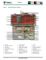
Figure 1
Ground & Test Device Front View ...................................................................7
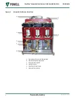
Figure 2
Ground & Test Device Rear View .....................................................................8
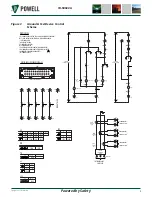
Figure 3
Ground & Test Device Control Scheme ...........................................................9
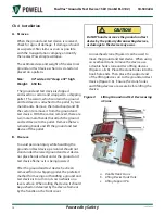
Figure 4
Lifting Ground and Test Device using a Crane .............................................10
Figure 5
Racking Access Handle .................................................................................16
Figure 7
Rotate Key in Lock “A” ...................................................................................16
Figure 6
Insert the Racking Handle ............................................................................16
Figure 8
Transfer Key from Lock “A” to Lock “B” ........................................................16
Figure 9
Sliding Safety Shutter to the Left ..................................................................17
Figure 10
Inserting Test Probes ....................................................................................17
Figure 11
Test Probes ....................................................................................................17

