Powered by Safety
®
18
Operation
PowlVac
®
Ground & Test Device 15kV (ConEd EI-4102)
IB-50022A
2) Procedure for Testing Feeder
a. Verify the Con Edison ground and
test device is being inserted in the
compartment of the feeder to be
grounded.
b. Insert the ground and test device in
to the compartment until a “stop” is
encountered.
c. Open the transparent guard
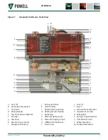
(Figure 1, aa) and depress the manual
trip operator (Figure 1, o) and pull down
on the racking access handle
(Figure 1, m) exposing the racking input
shaft.
PowlVac
®
racking handles incorporate a
built-in torque limiting feature in the design
that prevents excessive force from being
applied to the PowlVac racking mechanism.
Use only PowlVac racking handles to connect
or disconnect the ground and test device.
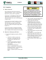
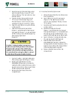
CAUTION
CAUTION
!
d. Insert a PowlVac racking handle into the
racking input shaft (Figures 5 & 6).
e. Rack the G&T device into the
CONNECTED position. Rotate the
racking handle (Figure 6) clockwise
until a positive stop is felt or the torque
limiter of the racking handle operates.
f. Follow Con Edison safety procedures
to ensure that the lower high voltage
connections in the compartment are
deenergized.
g. Close the G&T device using the remote
control switch.
h. Close the G&T device using the remote
control switch.
i. Rotate the key in Lock “A” electrically
disabling the G&T device (Figure 1, t).
Remove the key from Lock “A”. The G&T
is now electrically and mechanically
locked in the CLOSED position.
j. Transfer the key removed from Lock “A”
to Lock “B” and rotate (Figure 9). Lock
“B” unlocks the test port shutter.
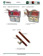
k. Open the test port shutter using the
slide handle to move the shutter fully to
the left (Figure 10). With the test ports
fully open the key in Lock “B” remains
captive.
l. Install the test probes into the test ports
(Figure 10). Move the test port shutter
to the right to capture the test probes
with the test probe shutter.
m. Rotate the key in Lock “B” to lock the
test probes in the test ports. The key in
Lock “B” is now available (Figure 8).
n. Transfer the key to key Lock “A” and
rotate (Figure 7). The G&T device
control circuit is now enabled. The key
in Lock “A” is captive.
o. Open the G&T device by using the
remote control switch.
The ground and test device is now prepared
for testing.
3) Removing the Test Probes
a. Close the G&T device using the remote
control switch.
b. Rotate the key in Lock “A” , electrically
disabling the G&T device (Figure 7).
Remove the key from Lock “A”. The
G&T device is now electrically and
mechanically locked in the CLOSED
position.
c. Transfer the key removed from Lock “A”
to Lock “B” and rotate (Figure 8). Lock
“B” unlocks the test port shutter.
d. Open the test port shutter using the
slide handle to move the shutter fully
to the left (Figure 9). With the test ports
fully open, the key in Lock “B” remains
captive.
e. Remove the test probes from the test
ports (Figure 10).


