background image

Powered by Safety

®

10

Installation

PowlVac

®

 Ground & Test Device 15kV (ConEd EI-4102)

 IB-50022A

Ch 4  Installation

A. R

ECEIVING

When the ground and test device is received, 
check for signs of damage.  If damage is found 
or suspected, file claims as soon as possible 
with the transportation company and notify 
the nearest Powell representative.

The estimated size and weight of the electrical 
ground and test device, when it is crated and 
placed on a pallet is:

Size: 

42” wide x 42” deep x 47” high

Weight: 650 

lbs.

 The ground and test device is shipped 
enclosed in a carton and strapped to a shipping 
pallet.  The carton, which contains the ground 
and test device is attached to the pallet by two 
metal bands.  Remove the metal bands and lift 
the carton to remove it from the ground and 
test device.  With the carton removed, there are 
two more metal bands that attach the ground 
and test device to the pallet.  Remove the two 
remaining bands and lift the ground and test 
device off the pallet.

B. H

ANDLING

To avoid personal injury while handling the 
ground and test device, personnel should not 
stand under the raised ground and test device 
nor place hands or feet under the ground and 
test device frame as it is being lowered.

After the ground and test device has been 
removed from its shipping pallet, the preferred 
method for moving and handling a ground and 
test device is to roll it on its own wheels on a 
lever surface.  When rolling the device, it should 
be pushed and steered by the device frame or 
by the handle on the front cover.   

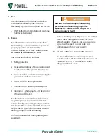
Do NOT handle or move the ground and test 
device by the primary disconnecting devices, 
as damage to the device may occur.

CAUTION

CAUTION

!

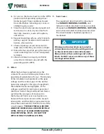
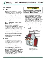
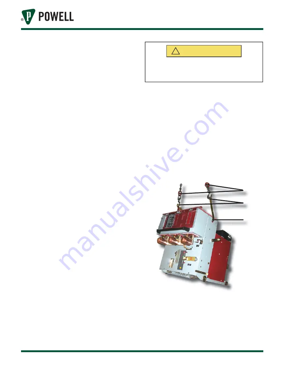
An overhead crane (Figure 4) can be used to 
move the ground and test device.  When using 
an overhead crane to move the device use 
a double hook crane and two lifting devices 
(Figure 4, a & b).  Place the crane hooks into the 
hook hole ends.  Then place the support end 
of the lifting devices on to the ground and test 
device (Figure 4, b).  Ensure the crane hooks 
and lifting devices are secure before lifting the 
device.

Figure 4 

Lifting Ground and Test Device using 
a Crane

a

b

c

a.  Double Hook Crane
b.  Lifting Device Hook Hole
c.  Lifting Support Pin

Summary of Contents for PowlVac 15GT36ASADE-23

Page 1: ...IB 50022A PowlVac Ground Test Device 15kV 15GT36ASDE 23 Electrically Operated Ground Test Device per Con Edison Specification EI 4102 Powered by Safety ...

Page 2: ...c Ground Test Device 15kV ConEd EI 4102 IB 50022A Contact Information Powell Electrical Systems Inc www powellind com info powellind com Service Division PO Box 12818 Houston Texas 77217 2818 Tel 713 944 6900 Fax 713 948 4569 ...

Page 3: ...ated in ANSI Z535 4 2002 4 13 4 13 3 as a signal word but used in this manual is IMPORTANT This is defined as IMPORTANT indicates a section of the manual covering a non hazardous situation but one where Powell feels proper attention is warranted IMPORTANT IMPORTANT Qualified Person For the purposes of this manual a qualified person as stated in NFPA 70 is one familiar with the construction and ope...

Page 4: ...Powered by Safety PowlVac Ground Test Device 15kV ConEd EI 4102 IB 50022A This page is intentionally left blank ...

Page 5: ...ICALLY OPERATED GROUND AND TEST DEVICE FOR USE 11 1 High Voltage Insulation Integrity 11 2 Vacuum Integrity 12 3 Control Voltage Insulation Integrity 12 E POWER GROUNDING SWITCH OPERATION 12 1 Closing 12 2 Opening 13 3 Electrical Operation Check 13 F INSERTING THE ELECTRICAL GROUND AND TEST DEVICE INTO THE METAL CLAD SWITCHGEAR 13 1 Electrical Ground and Test Device Inspection 14 Ch 5 Operation 15...

Page 6: ...OMMENDED RENEWAL PARTS 21 Figure 1 Ground Test Device Front View 7 Figure 2 Ground Test Device Rear View 8 Figure 3 Ground Test Device Control Scheme 9 Figure 4 Lifting Ground and Test Device using a Crane 10 Figure 5 Racking Access Handle 16 Figure 7 Rotate Key in Lock A 16 Figure 6 Insert the Racking Handle 16 Figure 8 Transfer Key from Lock A to Lock B 16 Figure 9 Sliding Safety Shutter to the ...

Page 7: ... cautions shall be abided by If there are any discrepancies or questions the user shall contact Powell immediately at 1 800 480 7273 WARNING WARNING Before any adjustment servicing part replacement or any other act is performed requiring physical contact with the electrical working components or wiring of this equipment the power supply must be disconnected Failure to follow this warning may resul...

Page 8: ... ordering renewal parts 6 Illustrations photographs and description of the circuit breaker The illustrations contained in this document may not represent the exact construction details of each particular type of ground and test device The illustrations in this document are provided as general information to aid in showing component locations only All illustrations are shown using deenergized equip...

Page 9: ...ergy exists ground the phase conductors or circuit parts before touching them Where it could be reasonably anticipated that the conductors or circuit parts being deenergized could contact other exposed energized conductors or circuit parts apply ground connecting devices rated for the available fault duty B SAFETY GUIDELINES Study this instruction bulletin and all other associated documentation be...

Page 10: ...must be observed 1 Do not close the grounding switch on an energized circuit The circuit to be grounded should always be treated as energized until proven otherwise 2 Use great care when opening the test port shutters to gain access to the test receptacles The test receptacles should always be treated as energized circuits until proven otherwise 3 Any test device plugged into the test receptacles ...

Page 11: ...eak voltage and the contact gap At the normal operating voltage for this type of equipment the radiation levels are negligible At the voltages specified for testing test personnel shall be in front of the ground and test device such that the two layers of steel used in the frame and front cover construction are between the test personnel and the vacuum interrupters and that the test personnel be n...

Page 12: ...ons the switch is prevented from opening electrically within a minimum of 20 seconds after closing B KEY LOCKS 1 Key Lock A Key lock A interlock is a single cylinder lock used to electrically enable or disable the G T device Figure 1 s Key lock A interlock is a single cylinder lock equipped with an electrical switch element The switch is CLOSED when the key is retained When the switch is OPEN the ...

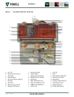
Page 13: ... Shutter Operator f Fastener g Test Ports h Test Port Cover clear i Equipment Housing j Instruction Plate k Front Handle l Racking Arm position m Racking Access Handle n Spark Gap o Manual Trip Operator p Manual Charging Crank q OPEN CLOSE Indicator r Front Cover s Lock A t Key 1 u Manual Close Operator v Operations Counter w Nameplate x Spring Charge Indicator y Anti Rollout Latch z Wheel positio...

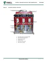
Page 14: ...Vac Ground Test Device 15kV ConEd EI 4102 IB 50022A Figure 2 Ground Test Device Rear View b d a c e f g a Secondary Disconnect Receptacle b Test Port Shutter Operators c Vacuum Interrupter d Glastic Barrier e Hex Head Cap Screws f Ground Connection ...

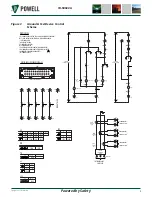
Page 15: ... 11 57 7 8 PIN NOT USED 8 6 4 2 7 5 3 1 16 15 19 20 21 22 23 24 X2 X1 CTA X2 X1 CTB X2 X1 CTC TO FEEDER CABLE POTHEADS LOWER STABS 3000 5A C400 3000 5A C400 3000 5A C400 AØ BØ CØ 15KV 36KA GROUND TEST DEVICE AØ DIFFERENTIAL CURRENT OUTPUT BØ DIFFERENTIAL CURRENT OUTPUT CØ DIFFERENTIAL CURRENT OUTPUT 24 23 21 22 19 20 LS LCS 57 103F 103F 15 17 13 14 103F 103E 11 12 9 10 CP 103E CP 109D 111D 114C 7 ...

Page 16: ...ersonal injury while handling the ground and test device personnel should not stand under the raised ground and test device nor place hands or feet under the ground and test device frame as it is being lowered After the ground and test device has been removed from its shipping pallet the preferred method for moving and handling a ground and test device is to roll it on its own wheels on a lever su...

Page 17: ...EPARING THE ELECTRICALLY OPERATED GROUND AND TEST DEVICE FOR USE Before shipment from the factory all functions of the ground and test device are thoroughly checked Powell recommends that prior to each use the ground and test device should be thoroughly checked and the following tests be performed in the sequence listed below 1 High Voltage Insulation Integrity 2 Vacuum Integrity 3 Control Voltage...

Page 18: ... leakage readings because a dielectric breakdown will trip all portable DC hipot test sets If a DC test breakdown occurs the test must be repeated after reversing the DC high voltage test supply connection across the vacuum interrupter Only when the vacuum interrupter has failed both tests should the operation condition be questioned No attempt should be made to try to compare the condition of one...

Page 19: ...f the control circuitry of the compartment used for test does not cause undesirable effects or unintended operation of other interconnected equipment such as supervisory control SCADA or automatic transfer schemes First remove the control fuses in the compartment Connect the jumper cable to the secondary disconnect plug in the compartment and to the G T Insert the fuses Operation of the G T contro...

Page 20: ...sure that disconnecting devices are in alignment and are not bent If damage or dirt is present see Ch 6 Maintenance A INSPECTION AND CLEANING If the primary disconnecting devices are damaged make no attempt to repair them Contact Powell immediately for further directions IMPORTANT IMPORTANT b Inspect the switchgear compartment to ensure that it is clean and clear of debris that might interfere wit...

Page 21: ...nt until a stop is encountered c Open the transparent guard Figure 1 aa and depress the manual trip operator Figure 1 o and pull down on the racking access handle Figure 1 m exposing the racking input shaft PowlVac racking handles incorporate a built in torque limiting feature in the design that prevents excessive force from being applied to the PowlVac racking mechanism Use only PowlVac racking h...

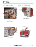
Page 22: ...02 IB 50022A Figure 5 Racking Access Handle a c b a Racking Shaft b Manual Push to Trip Button c Racking Access Handle Figure 6 Insert the Racking Handle a a Racking Handle Figure 7 Rotate Key in Lock A a a Key Lock A Figure 8 Transfer Key from Lock A to Lock B a a Key Lock B ...

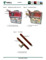
Page 23: ...iding Safety Shutter to the Left a b a Test Port Shutter Operators b Test Ports with Shutter Open Figure 10 Inserting Test Probes a b a Test Port Shutter Operators b Test Probe Figure 11 Test Probes a b a High Voltage Test Probe b Low Voltage Test Probe ...

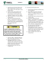
Page 24: ...ng the G T device Figure 1 t Remove the key from Lock A The G T is now electrically and mechanically locked in the CLOSED position j Transfer the key removed from Lock A to Lock B and rotate Figure 9 Lock B unlocks the test port shutter k Open the test port shutter using the slide handle to move the shutter fully to the left Figure 10 With the test ports fully open the key in Lock B remains captiv...

Page 25: ...lVac racking handle onto the racking input shaft Figures 5 6 k Racking the G T device into the DISCONNECTED position Rotate the racking handle counterclockwise until a positive stop is felt or the torque limiter of the racking handle operates l Remove the G T device from the compartment 4 Procedure for Removing Grounds a Obtain the key from the Con Edison lock box on premises b Insert the key in L...

Page 26: ...e recorded B INSPECTION AND CLEANING Inspect the ground and test device for loose or damaged hardware or parts Tighten any loose hardware and replace missing or damaged hardware or parts When necessary remove loose dust and dirt from the ground and test device with a vacuum cleaner a clean dry cloth or an industrial type wiper Do NOT use an air hose to clean the ground and test device Dirt or grit...

Page 27: ...letin or photo B RECOMMENDED RENEWAL PARTS A sufficient amount of stocked parts minimizes service interruptions caused by breakdowns and saves time and expense When continuous operation is a primary consideration a larger quantity of renewal parts should be stocked depending on the severity of the service and the time required to secure replacement parts Since parts may be improved periodically re...

Page 28: ...Powered by Safety PowlVac Ground Test Device 15kV ConEd EI 4102 IB 50022A This page is intentionally left blank ...

Page 29: ... Houston TX 77217 Tel 713 944 6900 Fax 713 948 4569 www powellind com info powellind com 2006 Powell Industries Inc All rights reserved 15GT36ASDE 23 Electrically Operated Ground Test Device per Con Edison Specification EI 4102 IB 50022A PowlVac Ground and Test Device 15kV January 2008 ...

Reviews: