


Publication No. 5106227
15
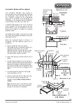
Guidance on Unusual Twin Flue Installations
The following notes offer guidance regarding the
relationship between the maximum flue length and the
number of bends allowed in a twin flue system.
In order to simplify the calculation, the following three
factors are used:-
1. Maximum System Factor
A figure of 100 is used and represents the maximum
resistance that can be applied to the appliance before
there is a notable reduction in its heat output.
2. Fittings Factor
This figure is calculated and represents the total
resistance of all the flue / air fittings in the proposed
system. e.g. bends, terminals and essential pipes such
as those rising from the boiler.
3. Pipe Factor
This figure is calculated and represents the remaining
resistance left for the flue / air pipe lengths in the
proposed system after subtracting (2) from (1).
Note:
Any flue and air pipe combination between the
minimum and maximum lengths may be used in
conjunction with any of the listed fittings, provided that
the Maximum System Factor of 100 is not exceeded.
Table of Flue Resistance Factors :
Component
factor
Mini Terminal (500 mm)
(each)
5.0
Pitched Roof Terminal
7.0
Vertical Terminal (inc. twin pipe adaptor)
6.6
60 mm Air / Flue Pipe - 0.25 m (each)
1.2
60 mm Air / Flue Pipe - 0.5 m (each)
2.1
60 mm Air / Flue Pipe - 1.0 m (each)
3.8
60 mm Air / Flue Pipe - 1.5 m (each)
5.5
60 mm Air / Flue Pipe - 2.0 m (each)
7.2
60 mm Air / Flue Pipe - 3.0 m (each)
10.6
Bend - 92°
4.0
Bend - 135° (45° Bend)
3.4
Bend - 150° (30° Bend)
2.6
Bend - 165° (15° Bend)
1.4
Note:
The above component factors are to be
cumulatively subtracted from the total system factor
of
100
(See Below)
.
Ensure that both
flue and air
pipes are counted.
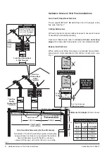
Worked Example
To calculate the maximum allowable air/flue pipe length
for the system shown in Fig. 21.
1. Establish the terminals, bends and essential
pipework (e.g. that rising from top of boiler) and add
the resistance factors obtained from the table above.
4 off 92° Bends
=
16.0 (4 x 4)
2 off 135° Bends
=
6.8 (2 x 3.4)
2 off Mini Terminals
=
10.0 (2 x 5)
Add: Essential Pipework -
2 off 1.5 m Air/Flue Pipes
=
11.0 (2 x 5.5)
Fittings Factor
=
43.8
2. Subtract this Fittings Factor from 100
i.e 100 - 43.8 = Pipe Factor =
56.2
3. Divide this Pipe Factor by the resistance factors
appropriate for the flue being designed.
e.g. 3 off 1 m Air/Flue Pipes =
11.4
6 off 2 m Air/Flue Pipes =
43.2
Total =
54.6
4. Compare this total of to the available Pipe Factor:
54.6
£
56.2 so this system is acceptable.
MAX0039B
Flue
Air
2 135˚
Bends
Factor
2 x 3.4 = 6.8
Factor
4 x 4 = 16.0
Factor
2 x 5.5 = 11.0
2 1.5m Pipes
above boiler
4 92˚
Bends
2 Mini
Terminal
Factor
2 x 5 = 10.0
Fig. 21
Guidance on Unusual Twin Flue Installations


