


Publication No. 5106227
6
Flue Air
Flue Air
Twin Flue
Pitched Roof
& Mini
Terminal
Example
Flue
Length
4m
Example
Air
Length
3m
Example
Flue
Length
4m
Flue Air
Loft
Space
Living
Space
Warning
Note that the length of the
Air Inlet Pipe MUST not be
less than
0.75 x length
of the Flue Pipe
Twin Flue Pitched Roof
& Mini Terminal
Example
Air
Length
2m
50mm
depth
Twin Flue Extension/
Bend Connection
Clean
Cut
Flue Pipe
Do Not Damage Internal Seals
with badly cut extensions
MAX0037A
Twin Flue
Double
Pitched Roof
Terminals
Badly
Cut
Flue Pipe
2˚ Angle
300mm max.
25mm min.
Void required for long flues
Flue Kit
Reqd.
5m
5m
7m
10m
Void
Length
3m
3.5m
5.5m
8.5m
Minimum
Void Depth
180mm
250mm
320mm
425mm
Minimum Void Depth
(320mm shown)
Twin Flue Mini Terminals (7m Flue Kit shown)
Ø60
1.5m
Schematic of 7m Mini Terminal flue system showing flue
rising vertically from boiler & rising towards the terminal.
Use Flue Brackets from kit 5106257 as shown to
secure Air/Flue pipes with a fall of 35mm in one metre.
1950mm
1950mm
Flue Brackets
Void Length
(5.5m shown)
Seal
Leave 5mm
clearance at
bottom of
each joint
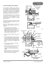
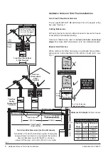
Guidance Notes on Twin Flue Installations
Twin Flue Pitched Roof Terminal
The air pipe MUST NOT BE LESS than 3/4 of the length of the
flue pipe. See Fig. 7.
Cutting Extensions
All flue components contain rubber lip seals to ensure both ease
of assembly and excellent sealing.
Care must therefore be taken to
remove all burrs and sharp
edges
from pipes which have been cut to non-standard lengths.
Expansion Allowance
When cutting and fitting flue pipes on extended flue systems,
allow approx. 5 mm clearance at the bottom of each joint - see
Fig. 7.
Fig. 7
Guidance Notes on Twin Flue Installations


