


Publication No. 5106226
12
MAX0033B
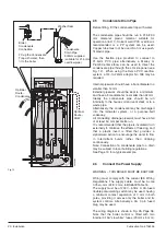
Flue Air
Flue Air
Flue Air
Twin Flue
Vertical
Terminal
Twin Flue
Double
Pitched Roof
Terminals
Side Concentric
Terminal
Twin Flue Mini
Terminals
Rear Concentric
Terminal
Twin Flue
Pitched Roof
Terminal
N
I
I
G
F
M
I
A
A
F
H
J,K
D
E
H
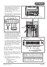
Likely flue positions requiring a flue terminal guard
C
R
A
I
J,K
I
L
T
S
B
Top View
Top
View
Concentric
Terminal
Assembly
Rear
Concentric
Flue
Side Concentric
Flue
300 min.
300 min.
MAX0027A
Top View
Mini Terminal Assembly
Property
Boundary
Line
Flue
Air
Property
Boundary Line
High Level
Side Twin Flue
300 min.
300 min.
Fig. 6
Installation Requirements
A
a
Directly below an opening, air brick,
opening windows, etc.
B
a
Above an opening, air brick, opening window, etc.
C
a
Horizontally to an opening, air brick,
opening window, etc.
D
Below gutters, soil pipes or drain pipes.
E
Below eaves.
F
Below balconies or car port roof.
G
From a vertical drain pipe or soil pipe.
H
From an internal or external corner.
I
Above ground, roof or balcony level.
J
From a surface facing a terminal.
K
From a terminal facing the terminal.
L
From an opening in a
carport
(e.g. door, window)
into the dwelling.
M
Vertically from a terminal on the same wall.
N
Horizontally from a terminal on the same wall.
R
From adjacent wall to flue (vertical only).
S
From internal corner to flue (vertical only).
T
Below eaves or balcony (vertical only).
Terminal Position with Minimum Distance (mm)
For IE, refer to I.S. 813 "Domestic Gas Installation".
Fanned Draught Balanced Flue
Note:
The distance from a fanned draught appliance terminal installed
parallel to a boundary may not be less than 300 mm in accordance with
the diagram on the left.
300
300
300
75
200
200
150
300
300
600
1200
1200
1500
300
210
230
600
a
In addition, the terminal should not be nearer than 150 mm to an opening
in the building fabric formed for the purpose of accommodating a built-in
element such as a window frame. See BS 5440 Pt. 1.


