PST-6000 series Technical Manual 5 - 5
TM
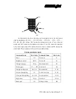
As illustrated in the above drawing, each rectangular dot in the font format
shall be identified as P11, P12,
…
, P15, P21, P22,
…
, P25, P31,
…
, P35,
…
, P71,
…
,
P75, P81, P82, P83. Where “Pn1” means the leftmost dot in the n
th
row of the dot
matrix and “Pn5” stands for the rightmost dot in the n
th
row. P81 means the round dot
to the lower right corner, P82 notifies the tail to form a comma and P83 denotes the
under mark. These notations will be used in user defined fonts.
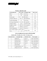
Futaba emulation mode
Command Name
Hex Codes
Command Name
Hex Codes
Reset
1F
Cursor on
13
Brightness control
04 bb
Cursor off
14
Change font page
1E 0p
(Horizontal tab.)
09
Moving sign
05
……
0D
(Line feed)
0A
Change leading code
06 x1 x2
Horizontal tab
11 09
Set pass through flag
01
Vertical scroll up
12 09
Clear pass through flag
x1 x2 02
Cursor up/down
11 0A
Digit select
10 pp
Line feed
12 0A
Back space
08
Carriage return
0D
P11
P15
P71
P75
P81
P82
P83
Summary of Contents for PST-6000 SERIES
Page 1: ...TM Rev A L 1 L 0 L P L 2 L 3 L 4 L 1 L 0 L P L 2 L 3 L 4 PST 6000 SERIES TECHNICAL MANUAL ...
Page 8: ...vi TM ...
Page 20: ...PST 6000 series Technical Manual 2 10 TM ...
Page 22: ...PST 6000 series Technical Manual 3 2 TM ...
Page 58: ...PST 6000 series Technical Manual 5 28 TM ...
Page 73: ...PST 6000 series Technical Manual 7 3 TM DWG 2 Unscrew the bottom ...
Page 77: ...PST 6000 series Technical Manual 7 7 TM DWG 7 Cable connections inside PST system ...
Page 82: ...PST 6000 series Technical Manual 7 12 TM ASSEMBLY DRAWING ...


