PST-6000 series Technical Manual 7 - 5
TM
DETACHING THE REAR CABINET
Before detaching the rear cabinet of the PST system, all the external devices
should be removed. Disconnect all the connectors in the rear room within back cover.
Refer to the installation instructions in User’s Manual (take opposite operation in
reverse order) for detaching CRT or LCD display, printer, VFD and if installed, the
built-in battery.
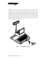
Look into both sides of the PST chassis, with reference to the following
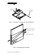
drawing, the user should find a “L” shaped steel wire at each side binding the rear
cabinet to the bottom chassis. Of course, only the short arm of the wire is visible from
the side that was covered by the side wall of the keyboard unit just removed. Turn the
short arms outward by 90 degrees (they were pointing upward) and pull the wires
toward the front till the long arms come out (see DWG.-5). Unscrew the two screws
and take out the washers on the printer platform to get ready to take the rear cabinet
off.
Now, the user would like it better to do the next operation with the PST system
up side down, though it is still possible for some skillful person to do it without
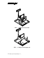
turning the PST. The drawing shows the bottom side of the PST system. The purpose
is to detach all the hooks from their notches. There are three notches on each side wall
of the bottom chassis and there are correspondingly three hooks at the inside of each
side wall of the rear cabinet. The key issue is to detach the hooks by pulling the side
walls of the rear cabinet a little bit outward yet still within the limit of the elasticity of
the cabinet (see DWG.-6). It is normal to have the rearmost pair of hooks more
difficult to get out than the others in this operation. Then the cabinet can be put aside
and the PST turned back to normal position.
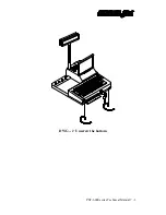
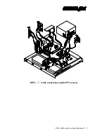
Refer to the drawing for cable connections within the PST system and
disconnect those necessary for taking out the module that needs to be replaced (see
DWG.-7).
Summary of Contents for PST-6000 SERIES
Page 1: ...TM Rev A L 1 L 0 L P L 2 L 3 L 4 L 1 L 0 L P L 2 L 3 L 4 PST 6000 SERIES TECHNICAL MANUAL ...
Page 8: ...vi TM ...
Page 20: ...PST 6000 series Technical Manual 2 10 TM ...
Page 22: ...PST 6000 series Technical Manual 3 2 TM ...
Page 58: ...PST 6000 series Technical Manual 5 28 TM ...
Page 73: ...PST 6000 series Technical Manual 7 3 TM DWG 2 Unscrew the bottom ...
Page 77: ...PST 6000 series Technical Manual 7 7 TM DWG 7 Cable connections inside PST system ...
Page 82: ...PST 6000 series Technical Manual 7 12 TM ASSEMBLY DRAWING ...


