PST-6000 series Technical Manual 5 - 2
TM
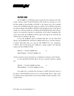
NVSRAM
The NVSRAM in a PST6000 system is installed in the mainboard of the PST
system. The basic model of the NVSRAM in a PST system has a memory size of 32
KB and addressed from D0000h to D7FFFh in the memory map. The expanded
version of the NVSRAM in the PST system has a memory size of 64 KB and occupies
the memory address from D0000h to DFFFFh. This arrangement gives a great deal of
easiness to a software programmer in utilizing the NVSRAM through direct software
control in the application program in consideration of the hardware upgrading. One
easiest way to utilize the NVSRAM of a PST system is through the use of the attached
software driver to simulate a disk drive.
To have the NVSRAM work as a simulated disk drive, the user should first
simply copy the NDISK.SYS file from the diskette attached to a convenient directory
of his/her Hard Disk Drive, say copy the file NDISK.SYS to the subdirectory
C:\PATH where PATH means the subdirectory routing required, add following
sentence into the CONFIG.SYS file:
DEVICE = C:\PATH \ NDISK.SYS
or
DEVICEHIGH = C:\PATH \ NDISK.SYS
and then restart the system. This will give a simulated free disk space of 28,160 bytes.
For the expanded NVSRAM option, the above sentence should be changed
into:
DEVICE = C:\PATH \ NDISK.SYS /S64
or
DEVICEHIGH = C:\PATH \ NDISK.SYS /S64
This option gives a simulated free disk space of 60,928 bytes after restart of
the system. The NVSRAM will then work as a simulated disk drive D: which works
not only faster than a hard disk drive but also more reliable and safer especially in case
of power failure.
Summary of Contents for PST-6000 SERIES
Page 1: ...TM Rev A L 1 L 0 L P L 2 L 3 L 4 L 1 L 0 L P L 2 L 3 L 4 PST 6000 SERIES TECHNICAL MANUAL ...
Page 8: ...vi TM ...
Page 20: ...PST 6000 series Technical Manual 2 10 TM ...
Page 22: ...PST 6000 series Technical Manual 3 2 TM ...
Page 58: ...PST 6000 series Technical Manual 5 28 TM ...
Page 73: ...PST 6000 series Technical Manual 7 3 TM DWG 2 Unscrew the bottom ...
Page 77: ...PST 6000 series Technical Manual 7 7 TM DWG 7 Cable connections inside PST system ...
Page 82: ...PST 6000 series Technical Manual 7 12 TM ASSEMBLY DRAWING ...


