PNC-2413 User’s Manual
11
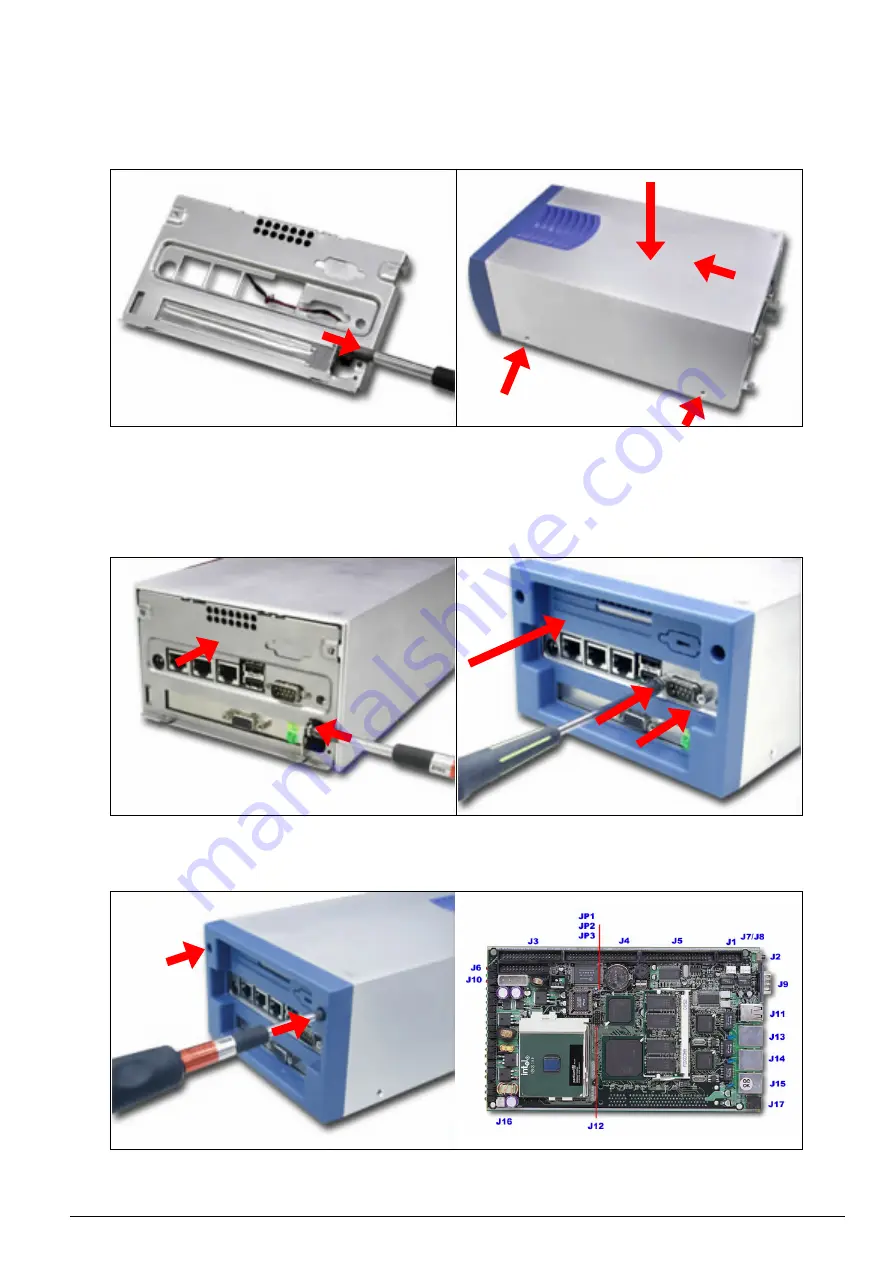
6. If there is an add-on PCI card, the original metal bracket needs to be removed (
Fig. 2-38
).
7. Apply downward force (
Fig. 2-39
¬
) and then slide toward the front panel (
Fig. 2-39
Á
). After
the cover is well tightly fit, put all four screws back to lock the top lead in position
(
Fig. 2-39
Â
).
Fig. 2-38
Remove the original metal bracket
Fig. 2-39
Place the top cover back to the unit
8. Put the steel back panel back to the system and lock the PCI card in position by a screw.
(
Fig. 2-40
)
9. Push the back panel till it clips (
Fig. 2-41
¬
). Then place both COM port bolts back (
Fig. 2-41
Á
).
Fig. 2-40
Fix the PCI card to the back panel
Fig. 2-41
Place the back panel in position
10. To finish up installation, drive two screws to lock up the back panel to chassis (
Fig. 2-42
).
Fig. 2-42
Lock the back panel
Fig. 2-43
Jumper Position
¬
Â
Á
¬
Á


