Page 16
EMHART TEKNOLOGIES
• 50 Shelton Technology Center, Shelton, CT 06484 • Tel. (877) EMHART1 • Fax: (800) 225-5614 •
www.emhart.com
Note:
Numbers in
bold type
refer to call out numbers in illustration.
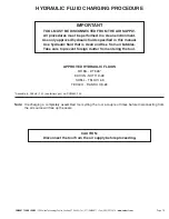
PROCEDURE
1. Loosen Fill Screw
10
.
2. Place the tool upside down in a soft jawed vise. Grip the tool gently on the aluminum casting in the middle
of the tool handle grip area.
3. Remove Clamp Screws
37
and
38
, Clamp Nuts
23
, Right Clamp
42
and Left Clamp
43
.
4. Remove Intensifier Chamber
45
, together with Intensifier Chamber Sleeve
46
. Take care not to loosen
O-ring
8
when removing these parts. Remove O-ring
8
.
5. Slowly withdraw the Intensifier Assembly
29
by pulling up on the air piston.
6. If Fill Screw
10
and Fill Screw Washer
4
have been removed during dismantling reinstall these before
proceeding and tighten hand tight.
7. Remove Nose Housing
44
.
8. Pull out on the Pulling Head Adaptor
28
(or push on the rear of the Hydraulic Piston Rod
26
) to ensure that
the Pulling Head Assembly (Hydraulic Piston) is fully forward.
9. Very slowly fill Ram Sleeve
32
with hydraulic fluid to the bottom of the chamfer. Take care to prevent
aeration of the hydraulic fluid.
10. Position Ram Assembly
29
over Ram Sleeve
32
and tilt slightly to immerse one edge of Ram Seal
40
into
the fluid, then straighten to fully immerse the seal without entrapping air. Push the Ram Assembly in as far
as it will go. The Hydraulic Piston Rod
28
will move rearward.
11. Remove Ram Assembly
29
and repeat steps 8, 9 and 10 above.
12. Remove the tool from the vise and stand it on the Air Piston on a flat surface.
13. Allow a few seconds for any entrapped air to rise in the tool before proceeding.
14. Place a spacer approximately 6mm (1/4 inch) thick between the Air Piston and the Handle
31
then slightly
loosen the Fill Screw
10
and slowly push down on the tool Handle expelling excess hydraulic fluid and
entrapped air from the Fill Screw hole. Continue pushing down until the Handle rests on the spacer.
15. Tighten Fill Screw
10
to torque specifications in Table 1, wipe Handle dry.
16. Lubricate the inside of Intensifier Chamber Sleeve
46
and the outside edge of the Air Piston Seal
30
.
17. Reassemble Intensifier Chamber
45
and Clamps
42
and
43
. Install Clamp Screws
37
and
38
and Clamp
Nuts
23
and tighten to torque specifications in Table 1.
18. Replace Nose Housing
44
and tighten to torque specification in Table 1.
19. Connect air supply to tool and check tool function and stroke length.

