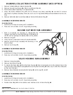
PULLING HEAD ASSEMBLY (HYDRAULIC PISTON)
1. Remove Nose Housing
44
(steps 1-7 in the
FRONT END ASSEMBLY
section of this manual), Intensifier
Chamber
45
and Intensifier Assembly
29
(steps 1-3 in the
INTENSIFIER ASSEMBLY
section of this
manual).
2. Remove Handle Cap Assembly
49
(PRT Option - see
HANDLE CAP ASSEMBLY
section of this manual) or
Mandrel Collection System Assembly (MCS Option - see
MANDREL COLLECTION SYSTEM ASSEMBLY
section of this manual).
3. Loosen but do not remove the Fill Screw
10
. Remove the tool from the vise. Invert the tool over a container
to drain hydraulic fluid from the Ram Sleeve
32
. Then remove Fill Screw
10
and Fill Screw Washer
4
. Allow
hydraulic fluid to drain out before continuing disassembly of the tool.
4. Using internal retaining ring pliers remove Sleeve Retaining Ring
18
.
5. Position the rear end of the Hydraulic Piston Rod
26
on a flat work surface and push down on the tool Handle
31
to push the Pulling Head Assembly out of the front of the Handle.
6. Firmly grasp the Pulling Head Adaptor
28
and gently but firmly pull the entire Pulling Head Assembly the rest
of the way out of the Handle
31
.
7. Using a 19mm (3/4") deep socket wrench on Hydraulic Piston Rod
26
loosen and remove Pulling Head
Adaptor
28
and slide Seal Sleeve assembly
25
off the Hydraulic Piston Rod.
8. To disassemble the Seal Sleeve
25
, remove Seal Snap Ring
20
using
internal retaining ring pliers. Remove Seal Retainer Washer
19
, Rod
Seal
17
, O-ring
41
and Piston Rod Seal
6
. Take care not to damage seal-
ing surfaces on the Seal Sleeve.
9. Using narrow nose pliers squeeze and pull to remove Piston Seal
27
.
Note: this is a two part seal - be sure to also remove the inner seal ener-
gizer ring. Do not reuse old seal or energizing ring. Take care not to
scratch the sealing surfaces of the Hydraulic Piston Rod
26
.
ASSEMBLE IN REVERSE ORDER
Assembly Notes:
1. Lubricate all O-rings and seals prior to installation.
2. Refer to torque specifications in Table 1 when tighten Pulling Head
Adaptor
28
to Piston Rod
26
and when installing Fill Screw
10
.
Before reinstalling the Pulling Head Assembly into the tool lubricate the
bore chamfer. Take care not to cut or damage Piston Seal
18
.
3. Do not force the Seal Sleeve
25
into final position. To seat the Seal
Sleeve, screw in the Nose Housing
44
to gently and slowly push the Seal
Sleeve into position then remove the Nose Housing and install the
Sleeve Retaining Ring
18
.
20
19
17
6
25
41
EMHART TEKNOLOGIES
• 50 Shelton Technology Center, Shelton, CT 06484 • Tel. (877) EMHART1 • Fax: (800) 225-5614 •
www.emhart.com
Page 11
Note:
Numbers in
bold type
refer to call out numbers in illustration.


