OPERATION
1. Attach Air Line
72
to air supply.
2. If so equipped, turn on the Mandrel Collection System by rotating the Switch/Deflector Ring
67
on the
Mandrel collector until one of the indicators is aligned with the arrow on the top of the tool. There are three
ON
positions so that the air exhaust may be directed away from the operator.
3. Insert a rivet mandrel into the Nosepiece
14
. If the tool is equipped with a Mandrel Collection System (MCS
Models) the rivet will be held in the tool by vacuum.
4. Guide the tool until contact is made between the face of the rivet head and the outer surface of the piece to
be riveted.
5. Squeeze the trigger
13
to set the rivet. Once the rivet is set, release the trigger. If using a PRT5400 or
PRT5400LS be sure to clear the mandrel from the tool by tipping the tool to let the mandrel slide either out
the front or out the back of the tool. If using the MCS5400 or MCS5400LS the mandrel will be automatical-
ly propelled into the mandrel Collector Bottle.
SERVICE PROCEDURES
CHANGING TOOL SET UP FOR DIFFERENT RIVET SIZES
To prevent mandrel jams from occurring and to maximize jaw life it is important to install the correct Nosepiece,
Jaws, Jaw Pusher and Mandrel Guide tube.
For
3/16" (4.8mm)
diameter or smaller rivets use the following parts:
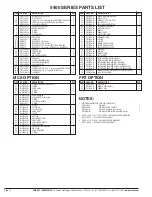
Item
3
Jaws, Part No. PRG540-46
Item
22
Jaw Pusher, Part No. PRT5500-6
Item
71
Mandrel Guide Tube, Part No. PRG540-43
Item
12
Nosepiece - PRN414 for 1/8" (3.2mm) diameter rivets
PRN524 for 5/32" (4.0mm) diameter rivets
PRN614 for 3/16" (4.8mm) diameter rivets
For
1/4" (6.4mm)
diameter rivets use the following parts:
Item
3
Jaws, Part No. PRG540-44
Item
22
Jaw Pusher, Part No, PRT5500-8
Item
12
Nosepiece - PRN811 for 1/4" (6.4mm) diameter rivets
(no Mandrel Guide Tube is required)
Equipment Needed:
7/16" (11mm) O.E. Wrench
Two adjustable wrenches 1" (26mm) or larger
Soft-jawed vise
Procedure
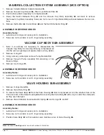
1. Place the tool in a soft-jawed vise, gripping the tool in the center of the handle.
2. Remove the Nosepiece
12
.
3. Remove the Nose Housing
44
.
4. Remove the Jaw Guide
11
, Jaws
3
and Jaw Pusher
22
.
5. Insert (or remove) the Mandrel Guide Tube
71
into the Jaw Pusher Spring
5
.
6. Install the correct Jaw Pusher
22
.
7. Install the correct Jaws
3
.
8. Re-install the Jaw Guide
11
and tighten to torque specifications in Table 1.
9. Replace the Nose Housing
44
and tighten to torque specifications in Table 1.
10. Install correct Nosepiece
12
and tighten to torque specifications in Table 1.
Caution:
Read the
Operator Instruction Leaflet
before operating the tool.
Note:
Numbers in
bold type
refer to call out numbers in illustration.
EMHART TEKNOLOGIES
• 50 Shelton Technology Center, Shelton, CT 06484 • Tel. (877) EMHART1 • Fax: (800) 225-5614 •
www.emhart.com
Page 7


