PONNDORF Gerätetechnik GmbH
Leipziger Strasse 374
D - 34123 Kassel
Operation Manual
Hose Pump Series
P_delta / PD-S
Page 15 of 29
Version 003_GB / 04.2021
5.3
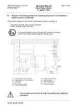
Diagram of the leakage detector for operating the pumps in non-hazardous
locations (art.-no. 93-000-009)
The following diagram is only valid for the leakage detector consisting of:
• capacitive proximity switch (make: Rechner)
• switch amplifier (make: Rechner)
The switch amplifier must not be used in hazardous locations.
It has to be strictly installed outside of these areas.
The connections must only be made by qualified and authorized
personnel!
A1
– switch amplifier type N-132/1-01
B1
– capazitive sensor (2-wire NAMUR)
F1
– control fuse
F2
– motor fuse
F3
– motor protection relais
H1
– control lamp-operation
H2
– signal horn, signal lamp
K1
– motor contactor
K2
– flasher relais 0,5 sec.
M
– motor – pump drive
S 1
– double push button
Summary of Contents for P delta 15
Page 1: ...Hose Pump Series P_delta PD S Operation Manual...
Page 2: ......


