


Operation
45
4
for absolute encoders or certain measuring devices such as resolvers, the phasing may be explicitly known from the
encoder angle. Consult the manufacturer's data sheet for more information.
4.4.4
Phase Initialization for Incremental Encoders
If an incremental encoder is used to provide continuous phase angle information to Atlas, some method is needed to
correlate measured motor angles with phase angle. There are a few commonly used approaches to accomplish this.
The first and simplest is to use Hall sensors. Upon initialization, the table in
Section 4.4.2, “Phasing with Hall Sensors”
is used to set up the phase angle. As the motor rotates thereafter, the encoder updates the phase angle. For highest
accuracy, the phase angle at the transition of one Hall state to another is used. In this manner the initial accuracy, equal
to one Hall state width of 60
°
can be improved to just a few electrical degrees, depending on how accurately the Hall
sensors were originally aligned by the motor manufacturer.
If Hall sensors are not available, a technique called algorithmic initialization can be used. In this approach, the
brushless DC motor coils are energized in a specific sequence and the resultant motor reactions are used to determine
the initial phase angle. Particularly for free-wheeling motors such as spindles, centrifuges, fans, and similar devices, this
approach can work well. However a detailed discussion of this is beyond the scope of this manual, so consult your
PMD representative for more information.
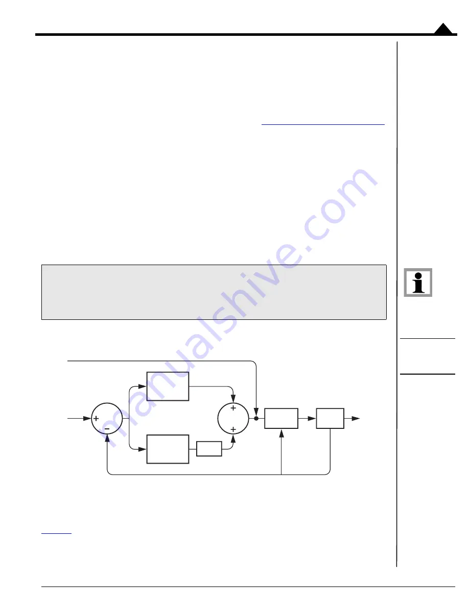
4.5
Current Loop
Figure 4-5:
Current Loop
Control Flow
Digital current control is a technique used with DC brush, brushless DC, and step motors for precisely controlling
the current through each winding of the motor. By controlling the current, response times are improved and motor
efficiency is increased.
provides an overview of Atlas unit’s current controller. For single-phase motors such as DC brush, one
current loop per axis is used. For brushless DC motors, two current loops are used and the third phase command is
Atlas
®
Digital Amplifier Complete Technical Reference
The next section describes a number of concepts that apply even when the current loop is not enabled. All Atlas
users should therefore read this section, whether they plan to operate the Atlas with a current loop, or without
a current loop in voltage mode.
to
motor
coil
Measured
Current
Foldback
Processing
Power
Stage
P
Proportional
I
Integral
I limit
Current
Command
Voltage
Command


