


Electrical Specifications
36
Atlas
®
Digital Amplifier Complete Technical Reference
3
3.9.4
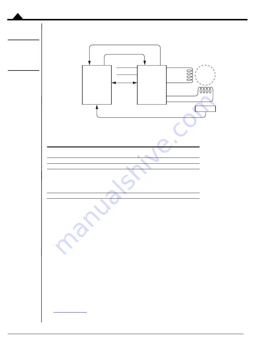
Step Motors Using SPI Communications
Figure 3-11:
Step Motor
SPI Communi-
cation Connec-
tions
The following table summarizes the recommended connections when connecting Atlas amplifiers to two-phase step
motors when using the SPI communications channel. In this mode the external controller provides position
commands to Atlas via the SPI interface.
These connections apply to bipolar motors. If connecting to unipolar motors do not connect the center tap.
In this configuration the external controller generally consists of a PMD Magellan Motion Processor, a programmable
microprocessor or DSP-type device, or a FPGA (field programmable gate array). The external controller provides a
continuous stream of position commands or individual phase torque output commands to control the motor position.
3.10 Heat Sink Grounding
The heat sink may be left ungrounded or may be connected to chassis ground for best EMI protection. The heat sink
should not be connected to the Atlas Pwr_Gnd.
3.11 Atlas Conversion Factors
The following table provides electrical conversion factors for the various Atlas units. These factors convert Atlas
command values specified via the Atlas unit's digital SPI interface (referred to as counts) to physical quantities such
as amperage or volts, and vice versa. For more information on the Atlas functions related to these conversion factors
see
.
Type
Required Signal Connections
Optional Signal
Connections
Power
HV, Pwr_Gnd
Communication
~SPICS, SPISO, SPISI, SPIClk, GND
Motor, Phase A
+
:
Motor, Phase A
-
Motor, Phase B
+
:
Motor, Phase B
-
:
Motor A
Motor B
Motor C
Motor D
Miscellaneous
~Enable
FaultOut
Enable
FaultOut
Optional Encoder Feedback
Encoder
Atlas
®
Digital
Amplifier
2 - Phase
Step
Motor
External
Controller
SPI
SPICS
SPIClk
SPISI
SPISO
Optional
Motor C
Motor D
Pwr_Gnd
HV
Motor A
Motor B


