


Operation
40
Atlas
®
Digital Amplifier Complete Technical Reference
4
In addition to providing a stream of torque or voltage commands, the external controller is used to set up operational
parameters needed by Atlas such as control gains, safety-related parameters, and other information. These parameters
may be provided to Atlas at each power up, or stored non-volatilely on Atlas so that they no longer need to be loaded
at each power-up. See
for more information on non-volatile parameter storage.
Communication to/from Atlas occurs via an SPI interface and associated protocol that uses packet-oriented
commands to specify various Atlas parameters, and, if desired, request status information from Atlas. This protocol
has been designed for maximum speed and flexibility so that torque or voltage commands can be continuously sent
to Atlas even while the external controller queries Atlas for various information. See
for more information on the SPI interface.
When Atlas is used in a higher level system such as a servo-based velocity or position controller, torque commands
are typically sent to Atlas continuously, at the motion controller’s servo rate. For most systems this rate is in the 1,000
to 10,000 samples per second range. However Atlas may also be used with direct voltage or torque control applications
that utilize Atlas to specify a desired output value just once after power-up, or only occasionally as required by the
application.
To disable Atlas operations it may be powered down, the
Enable
signal may be de-asserted, or various commands that
result in Atlas operations being suspended may be sent by the external controller to Atlas through the SPI interface.
In addition, there are several conditions where Atlas automatically shuts down for safety-related reasons. These may
include short circuit detection, under and over voltage protection, I
2
t current limiting, and amplifier over temperature
Section 4.8, “Safety Processing Functions”
for more information on emergency stop and related
functions.
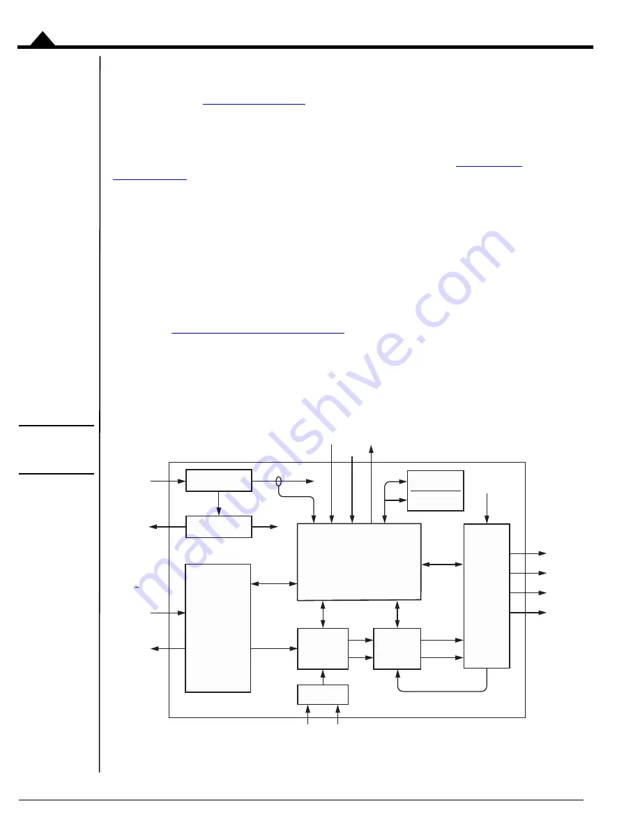
4.2
Internal Block Diagram
Figure 4-2:
Internal Block
Diagram
Atlas
®
Control
Processor
AtRest
Power
Stage
SPI
Command
Processor
Pulse and
Direction Counter
Pulse Direction
NVRAM
Trace
RAM
Digital
Current
Loop
Commutation
&
Microstep
Control
HV
5V
Bus Monitoring
Bus Voltage
Bus Voltage
Motor
Outputs
~Enable
FaultOut
Current Sense
DC Bus
Logic Supply
+ 3.3 V
A
B
C
D
A
B
A
B
SPISO
SPICS
SPIClk
SPISI


