0507347110/160114/B SHIELD fire safety solutions (5k1)
| INSTALLATION | EN - 20
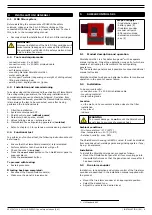
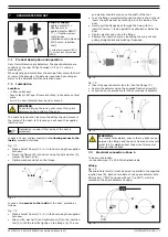
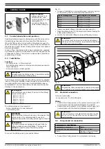
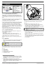
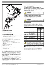
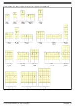
Fig. 11.2
11.3 Electrical connection
To be sourced locally:
- connection wire: 5 x 20 AWG
Connection to ShieldControl 5k1
•
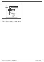
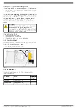
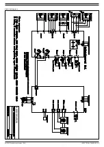
Place an EOL diode supplied with the ShieldControl in the
junction box in series over each FlameShield, in accordance
with the electrical diagram on page 29.
11.4 Post installation checks
Before performing the functional test, check the following
mounting instructions.
•
Wiring from and to the ShieldControl.
•
EOL resistor-diode in junction box.
•
Correct position and flow angle (10°) of FlameShield
generator.
•
Tightening of bolts and nuts.
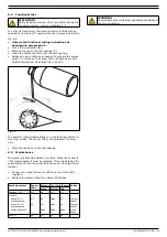
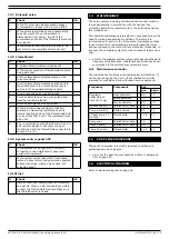
11.5 Functional test
A functional test can be done in two ways:
- by a simulation
- true functional test
11.5.1 Simulation
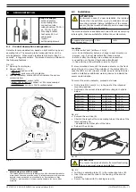
Two heat resistant wires are connected to an internal metal
spiral activator in the FlameShield generator. The spiral is
heated by the current and starts an exothermic chemical
reaction that releases the aerosol. The minimum amount of
energy needed to start the reaction is supplied by 12V/0.8 A
during 3-4 seconds.
The internal wiring of the activator can be inspected by
measuring the internal ohm resistance of 2 ohm +/- 0.2 ohm
with an ohm meter with a current less than 5 mA. This
inspection can be done in the junction box mounted on the
outside of the filter by measuring the ohm resistance over the
heat resistant wires.
•
Check electrical activation of the FlameShield modules
according to the above instruction.
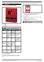
11.5.2 True functional test
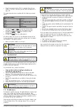
A true functional check can be done by replacing the
FlameShield module with the detonation simulator supplied and
create a fire condition (e.g. by removing one of the spark
detectors). After fire alarm the detonation simulator will be
activated showing a small flash.
•
Perform a true functional test as described above.
•
Reset activated detector (refer to relevant chapter).
•
Press the
SYSTEM RESET
button on the ShieldControl panel.
•
Reconnect the FlameShield module(s).
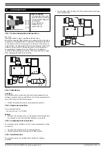
11.6 Maintenance
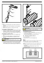
During the lifespan of FlameShield, the generators must be
inspected periodically in accordance with the national fire
protection association requirements or the authorities having
local jurisdiction.
Due to their chemical composition and characteristics, the
FlameShield generators do not require any inspection and
maintenance during their lifespan.
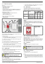
E
D
C
F
B
A
MDB
WARNING
Use Personal Protective Equipment (PPE) to protect
from exposure to sparks.
WARNING
Keep away from inflammable material and do not hold
in the hand.
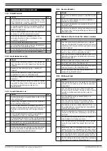
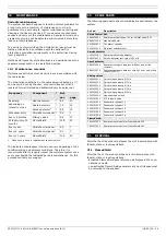
Component
Action
Frequency:
at least
every 12
months
every 10
years
Metal holder
Check for damage, corrosion
and correct position.
X
Support bracket Check for damage, corrosion
and correct position.
X
System wiring
connections and
circuit
Check proper wiring and
circuit.
X
FlameShield
internal
activation
Check internal activation;
X
Aerosol
generator
REPLACE. X
WARNING
When the filter installation with FlameShield
generators is placed in an area where it is exposed to
vibrations due to e.g. heavy machinery, more frequent
inspections are needed to secure correct positioning.
Put a sticker on the FlameShield generator(s) stating
the installation date and/or keep a log.

