0507347110/160114/B SHIELD fire safety solutions (5k1)
| INSTALLATION | EN - 16
9.1
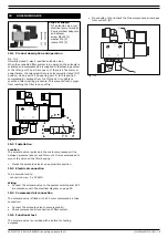
Product description and operation
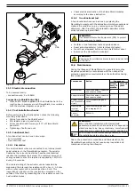
Double activated pneumatic sliding valve with 5/2 solenoid, to
be installed by two pieces (before and after filter system).
When the filter system is in operation the valves are open. In
case of an alarm or power failure or when the fan is switched off
the valves are closed. Correct closing of the valves is monitored
by the reed contact.
In case of fire, the sliding valves close automatically, operated
by pneumatic cylinders. In sequence to a lack of oxygen the fire
is supposed to choke. This will also minimize risk of escalation
or spreading of smoke.
9.2
Installation
Location:
- 1st sliding valve: in filter inlet duct
- 2nd sliding valve: before or after spark and smoke sensors in
filter outlet duct
- to be mounted in vertical position
It is strongly recommended that the sliding valves be installed
indoors. If they are installed outside, however, ensure that they
are protected from rain and snow. Avoid installation where
compressed air can cool down below its dew point to prevent
damage to the pneumatics.
The sliding valves can be mounted:
- during installation of a new ductwork
- in an existing duct
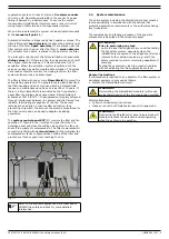
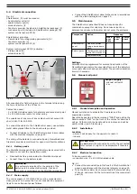
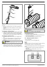
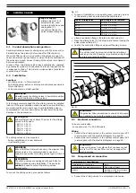
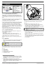
To mount the sliding valves, proceed as follows.
In case of installation in an existing duct: cut away a piece
of the existing duct as indicated in the table below.
•
Slide a connection flange (B) into both duct ends (A).
•
Place the sliding valve (D) in between and fasten it using the
quick release clamps (C).
•
Fasten the connection flanges using self-tapping screws.
Fig. 9.1
9.3
Electrical connection
To be sourced locally:
- connection wire: 5 x 20 AWG cable
Wiring
•
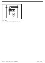
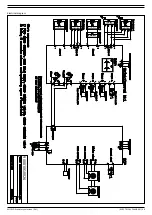
Connect the sliding valves to the system control panel SCP
in accordance with the electrical diagram on page 29.
•
Connect the reed contacts to the system control panel SCP
in accordance with the electrical diagram on page 29.
9.4
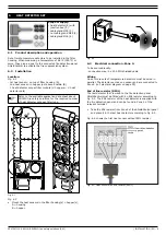
Compressed air connection
•
Connect the sliding valves to a compressed air source.
9
SLIDING VALVES
Scope of supply:
- sliding valve incl. 5/2
solenoid valve, reed
contact, junction box and
cable gland (3)
- connection flange (2)
- quick release clamp (2)
WARNING
Do
not
mount the sliding valves in horizontal position
to avoid malfunction of the valves.
ATTENTION
Allow sufficient space above the duct for the sliding
valves to fully open;
- SV-10: + 14 in.
- SV-12: + 16 in.
- SV-16: + 20 in.
- SV-20: + 26 in.
- SV-24: + 32 in.
WARNING
Ensure that the ductwork can carry the weight of the
sliding valves. It is recommended to use duct
supports, especially for sliding valves type SV-16/20/
24.
ATTENTION
The sliding valves are equipped with eye bolts for
lifting purposes during installation. The eye bolts
cannot
be used to mount the sliding valves
permanently.
Type of sliding valve
Duct length to be removed
SV-10
11.6 in. +/- 0.4 in.
SV-12
11.6 in. +/- 0.4 in.
SV-16
11.6 in. +/- 0.4 in.
SV-20
15.0 in. +/- 0.4 in.
SV-24
15.0 in. +/- 0.4 in.
WARNING
The valves must be mounted straight and without
tension on the shell/housing to guarantee airtightness
and to avoid noise by airflow.
WARNING
If applicable, take precautions to ensure that people
are not able to get into the blade's arc of movement.
WARNING
Keep wiring away from places that can become hot
due to fire. Do not use filter or duct as support for
electrical wires.
Compressed air specifications
Compressed air connection
6 mm
Recommended operational pressure
5 bar (max. 9 bar)
Quality
dry and oil-free according to
ISO 8573-3 class 6
B
A
B
A
C
D
C

