background image

E-27

Scanning Adjustment (White Calibration)

If dark lines (horizontal black lines) on a printed out hard copy or image on the screen are generated, you need 

to optimally adjust the sensitivity of reading the sheet surface.

If the scanning image does not work due to generation of dark lines, update the program and perform the white 

calibration in the following steps.

Preparation:

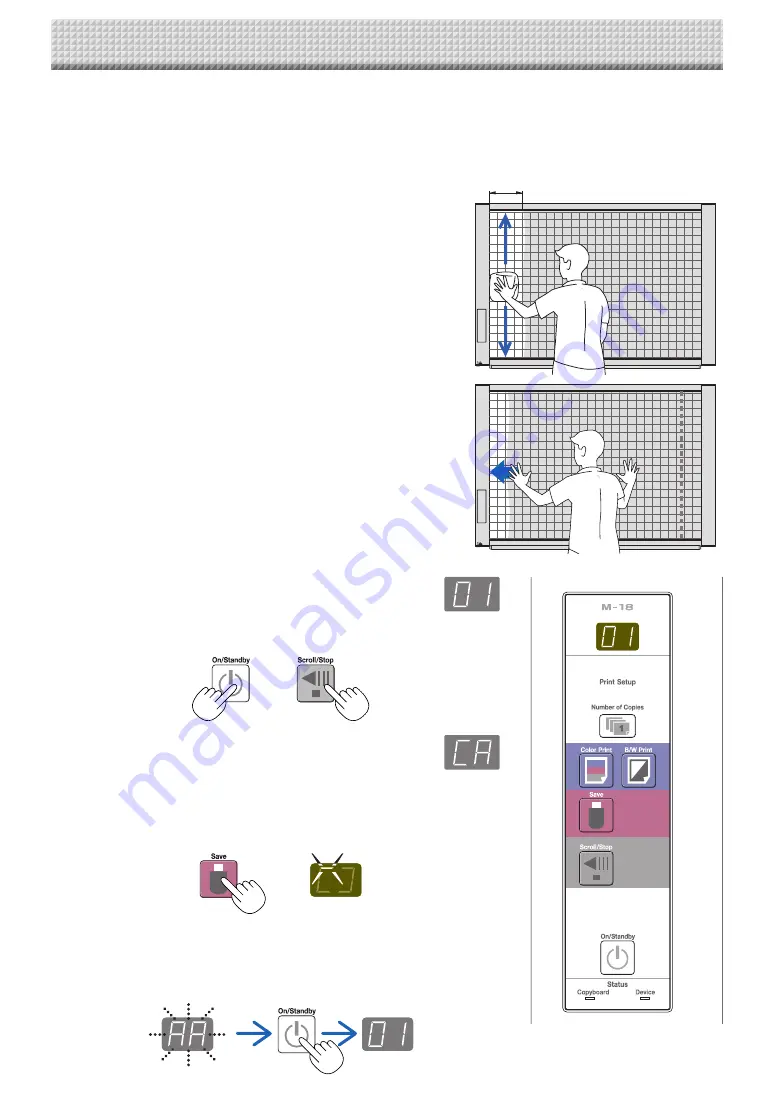
1.  Use the supplied white board cleaner or damp cloth to 

clean the 20 cm of width on the left edge of the main unit.


Avoid cleaning the joint part of the sheets. Doing so may cause 
incorrect calibration.

20 cm or longer

2.  Feed the sheet manually until the half width of cleaned 

sheet is covered by the frame of the main unit.

Operation

1.  Make sure that the main unit’s power is turned on.
 

(Display on the display window is “01”.)

2.  Press the Scroll/Stop button (on the left) while pressing and holding 

the On/Standby button.

3.  Release the buttons.
 

The display “CAL” will be changed.


* “CA” 

 “AL” 

 “L” in this order

4.  Press the Save button.
 

The display on the display window starts rotating and adjusting automati-
cally.

5.  When the display on the display window is flashing “AA”, press the 

On/Standby button.


The display on the display window returns to “01”, indicating that the 
reading adjustment is completed.

Summary of Contents for M-18S

Page 1: ...Thank you for your purchase of the PLUS Copyboard Please read this User s Manual carefully before use to take full advan tage of the functions of this product After you have finished reading the manual please keep it for future reference ...

Page 2: ... be given due respect Product names and company names appearing in this manual are registered trademarks or trademarks of the respective compa nies 1 The contents of this manual may not be reprinted in part or whole without permission 2 The contents of this manual are subject to change without notice 3 Great care has been taken in the creation of this manual however should any questionable points ...

Page 3: ...E 5 Input output terminals E 6 Changing the Height of the Unit E 7 Control Panel E 8 Operation Steps E 9 Connecting the Power E 10 Printing printer sold separately E 11 Preparing the Printer E 11 Basic Printing Operation E 12 Moving the sheet surface manually E 13 Using USB Memory E 14 USB Memory Storage Procedure E 14 Using the copyboard connected to a computer E 17 CB Setup Procedure E 18 CB Set...

Page 4: ...ll brackets 2 Main unit fixing screws M4 12 2 Sold separately for some products Dedicated eraser 1 Use this to erase the drawing Copyboard Accessories Dedicated markers One each of black red blue and green Use these markers to draw on the sheet surface AC power adapter with power cord 1 This is the power adapter for supplying power to the copy board See Page E 10 USB cable type B type A 1 PLUS cod...

Page 5: ... copyboard and printer here See the Assembly and Setup Manual Stand This stand supports the copyboard See the Assembly and Setup Manual Main unit Pen tray Depending on the product you have purchased the printer may be sold separately This illustration does not show the connection cords Effective Reading Size The area that can be copied is the gray area of the diagram Note It might not be possible ...

Page 6: ...edicated USB port Type B Connect this with the USB port type A of the PC Used to connect the copyboard to a computer to make the copyboard s device settings Can also be used to copy scanned images onto the computer See page E 17 E 22 The connector is located on the bottom sur face of the main unit The diagram view is seen from the bottom Names of the Parts Unlock Lock Caster Locking unlocking the ...

Page 7: ...his illustration does not show the connection cords Mounting hole Hook lock screw Rear frames lock screws Stand CAUTION At least two persons should hold the main unit If not the main unit could drop or tip resulting in accidental injury Lock the stand s casters by pressing the bottom of the caster lock button If not the stand could move while the main unit is being mounted or removed resulting in ...

Page 8: ...f copies indicated on the display window 5 B W Print button The sheet is moved by 1 screen and read and the image is printed in black and white in the number of copies indi cated on the display window 6 Save button USB memory storage The sheet is moved by 1 screen and read and the image is stored on the USB memory device When connected to a computer by USB cable the image is stored in the copyboar...

Page 9: ...int button is pressed or stored as image data on the USB memory device or in the main unit s internal memory when the Save button is pressed Preparation Set up the newly purchased copyboard and connect a printer See a separate manual titled Assembly and Setup Manual Plug the AC power plugs of the copyboard and printer into wall power outlets See page E 10 After purchase be sure to set the copyboar...

Page 10: ... use the copyboard connect the copyboard s AC power plug to a wall power outlet The main power turns on In this manual this is referred to as the standby mode The descriptions in this manual assume that the AC power plug is connected that the unit is in the standby mode About the printer s power supply When using a printer connect its power plug to a wall power outlet Also turn on the printer s po...

Page 11: ...ions for a description of the paper that can be used Discharge tray Paper guide Paper Power switch Appearance of printer is for illustration purposes Paper tray Switch on the power Press the power switch The power indicator lights This completes the preparation of the printer Press the Color Print or the B W Print button on the copyboard s control panel One page worth of data is read and the print...

Page 12: ... To stop the operation part way through press the Scrol Stop button again Note The one screen that is visible is printable position To fine adjust the sheet surface position with the sheet stopped move the sheet slowly by hand The sheet can be moved either to the left or to the right Printing of the portion located around the sheet surface might not be pos sible Please see Effective reading size o...

Page 13: ...e image on the sheet surface see Making the Device Settings page E 22 A flashing in the display window indicates a print error See Meaning of Error Messages on Page E 24 When printing a time stamp date and time is printed at the top right of the sheet See Making the Device Set tings on page E 22 When the copyboard is not going to be used press the ON Standby button and switch off the power standby...

Page 14: ... be used 4 If the USB flash memory device is divided into multiple partitions only one partition can be recognized with this unit See the PLUS website for more information on USB memory devices usable with this unit USB Memory Storage Procedure Preparation Check that the copyboard s AC power plug is connected to a wall power outlet See page E 10 Press the ON Standby button and switch on the power ...

Page 15: ... may take time for recognition or it may take time for saving When the ON Standby button is pressed during the reading operation the reading operation will be discontin ued and the partially read image data will be stored in the USB memory To move the sheet surface wait until scrolling stops then press the Scroll Stop button The date and time of the saved file will reflect the copyboard time setti...

Page 16: ...mounted Unplugging the USB memory device will switch off the power A function that serves as a reminder to unplug the USB memory device When the copyboard and a computer are connected by USB cable the auto power off function which turns the power off automatically is canceled Scanned images files stored in the copyboard s internal memory are cleared when the power is turned off set to standby with...

Page 17: ...possible Turn on the copyboard s power and connect the PC dedicated USB port type B and com puter using the USB cable The standard driver is installed automatically and the copyboard is identified by the computer as a removable device To computer s USB port type A USB cable included with copyboard To PC dedicated USB port type B Press the Save button to store Display window Flashing indicator rota...

Page 18: ...ber then press the Save button Press the Number of Copies button the func tion switches each time the button is pressed returning to F1 after FA to select the desired function number then press the Save button to set that function number For the item names of the function numbers see the Table of Function Numbers and Settings on the following page When the Save button is pressed the func tion numb...

Page 19: ...g ex circles become ellipses Compressed Lit Off Equal Ratio Off Lit Color Printing If this is set to Invalid color printing is not possible Valid When this is set color printing is possible Invalid When this is set color printing is not possible Valid Lit Off Invalid Off Lit Graphics File Format Selection of the format in which image files are saved Scanned images are converted into JPEG extension...

Page 20: ... to set the current date and time If the ON Standby button is pressed during steps 3 to 5 the partially made setting is canceled and the date and time return to the values set before the set ting was started 5 Complete the setting When the Save button is pressed after the minute s setting position c 6 display has been set the Time Setting is completed and the F1 display CB Setup reap pears Press t...

Page 21: ...h then press the Save button to enter The display switches to c4 setting of day Use the Color Print Increase and B W Print Decrease buttons to select 08 the day then press the Save button to enter The display switches to c5 setting of hours Use the Color Print Increase and B W Print Decrease buttons to select 14 the hours then press the Save button to enter The display switches to c6 setting of mi...

Page 22: ...s being accessed from the computer The response time could be long and the operation may not be possible Turn on the copyboard s power and connect the PC dedicated USB port type B and com puter using the USB cable The standard driver is installed automatically and the copyboard is identified by the computer as a removable device To computer s USB port type A USB cable included with copyboard To PC...

Page 23: ...ter size 1 for A4 size Printing Image Stretch Set to 0 to print the image as it is on the sheet surface Set to 1 to fit the image to the printing paper Only settable for wide type copy boards Color Printing Color Printing Set to 0 color printing is possible Set to 1 color printing is not possible Image file format Graphic File Format Set to 0 for JPEG 1 for PNG 2 for PDF Do not input spaces If thi...

Page 24: ... memory storage again Do not insert or remove the USB memory during processing Reading prob lem There is a lighting fault of the reading light source or a read signal error Unplug the power plug from the power outlet and then plug it in again System error There is a memory or internal fault Unplug the power plug from the power outlet and then plug it in again Color printing prohibited Color printi...

Page 25: ...tact your nearby PLUS Corporation sales office dealer or store Condition Please Check Printer Related The copyboard s power turns on but the printer s power does not Check whether the printer s power plug DC plug is securely inserted If the power still does not turn on disconnect the AC adapter box and check whether the printer s AC power adapter side plug is unplugged from the AC power adapter Fo...

Page 26: ... Check the print Is the each color line printed uniformly Are there missing dots pale lines lines with thinner ink than others etc Remedy If the nozzle is partially choked clean it If the quality of the print does not improve even though the nozzle has been cleaned wipe off the ink on the surface of te nozzle For details see the User s Guide included with the printer Please see your printer manual...

Page 27: ...he sheets Doing so may cause incorrect calibration 20 cm or longer 2 Feed the sheet manually until the half width of cleaned sheet is covered by the frame of the main unit Operation 1 Make sure that the main unit s power is turned on Display on the display window is 01 2 Press the Scroll Stop button on the left while pressing and holding the On Standby button 3 Release the buttons The display CAL ...

Page 28: ...nterface USB2 0 4 Printing Printing resolution 300 dpi or equivalent No print colors 16 or grayscale Printer interface Conforming to USB 2 0 standards Added functions Clock Used for the timestamp and for file dating properties Includes backup battery for when there is a loss of power Battery life Approx 00 hours PC connection Images can be acquired and device settings made via USB using a browser ...

Page 29: ...ied with the printer To USB connector Printer To DC connector Printer AC power adapter supplied with the printer To wall power outlet To DC INPUT connector AC power adapter supplied Appearance of printer is for illustration purposes Note The AC power adapters of accessories and printers that have been verified to be operation many differ from the ones shown on the connections diagram they may be o...

Page 30: ... 2011 PLUS Corporation 26 4601 11D ...

Reviews: