background image

User Manual of WNAP-7206 


-56- 


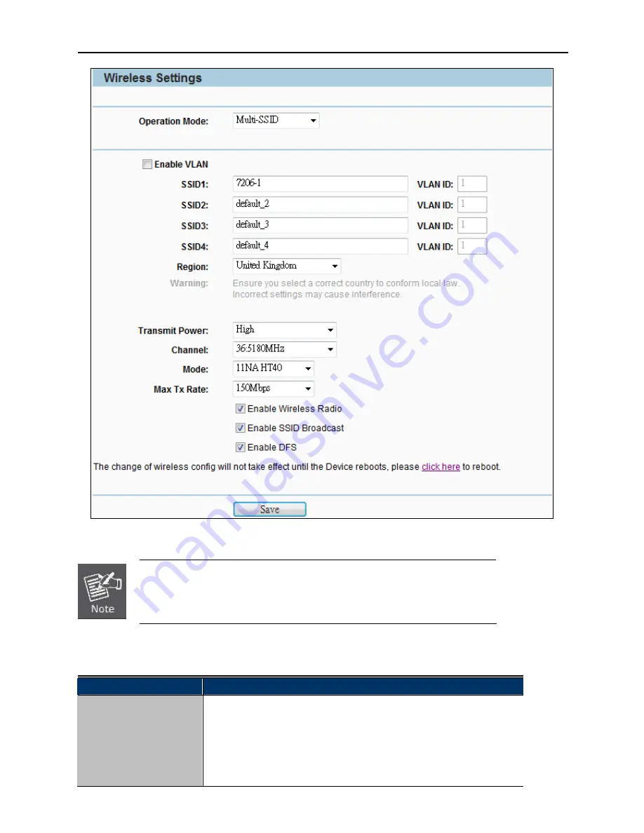
Figure 5-6-1-2

 Multi-SSID Mode 


First at all, you should select your location, save it and reboot, or you may not 

search any APs. Ensure you select a correct country to conform local law. 

Incorrect settings may cause interference.


The page includes the following fields: 

Object 

Description 


Enable VLAN 

Check this box to enable the VLAN function. The AP supports up to 4 

VLANs. All wireless PCs in the VLANs are able to access this AP. The AP 

can also work with an IEEE 802.1Q Tag VLAN supporting Switch. If this 

Switch enables the Tag VLAN function, besides all wireless PCs, only the 

PCs in the VLAN same with SSID1 are able to access the AP. If a PC is 

Summary of Contents for WNAP-7206

Page 1: ...User s Manual www PLANET com tw 802 11a n Wireless Outdoor AP WNAP 7206 ...

Page 2: ...5 of the FCC Rules These limits are designed to provide reasonable protection against harmful interference when the equipment is operated in a commercial environment This equipment generates uses and can radiate radio frequency energy and if not installed and used in accordance with the instruction manual may cause harmful interference to radio communications Operation of this equipment in a resid...

Page 3: ...in the Mode field the Channel Width selecting field will turn grey and the value will become 20M which is unable to be changed Enable Wireless Radio The wireless radio of this Router can be enabled or disabled to allow wireless stations access Enable SSID Broadcast When wireless clients survey the local area for wireless networks to associate with they will detect the SSID broadcast by the Router ...

Page 4: ... of the equipment WEEE regulation To avoid the potential effects on the environment and human health as a result of the presence of hazardous substances in electrical and electronic equipment end users of electrical and electronic equipment should understand the meaning of the crossed out wheeled bin symbol Do not dispose of WEEE as unsorted municipal waste and have to collect such WEEE separately...

Page 5: ...ation Precautions 12 3 3 Hardware Installation 14 3 4 Pole Mounting 16 3 4 1 Using the External Antenna 16 Chapter 4 Quick Installation Guide 17 4 1 Manual Network Setup TCP IP Configuration 17 4 1 1 Configure the IP Address Manually 17 4 2 Starting Setup in the Web UI 21 Chapter 5 Configuring the AP 25 5 1 Status 25 5 2 Quick Setup 28 5 3 WPS 28 5 3 1 Push Button Config PBC 29 5 3 2 PIN Input Con...

Page 6: ... 5 Operation Mode Universal Repeater 84 5 6 2 6 Operation Mode Bridge with AP 86 5 6 2 7 Operation Mode AP Router 88 5 6 2 8 Operation Mode AP Client Router 91 5 6 3 Wireless MAC Filtering 93 5 6 4 Wireless Advanced 94 5 6 5 Antenna Alignment 96 5 6 6 Distance Setting 96 5 6 7 Throughput Monitor 98 5 6 8 Wireless Statistics 99 5 7 DHCP 99 5 7 1 DHCP Settings 100 5 7 2 DHCP Clients List 101 5 7 3 A...

Page 7: ... 8 Reboot 141 5 16 9 Password 141 5 16 10System Log 142 5 16 11 Statistics 145 Appendix A FAQ 147 A 1 What and how to find my PC s IP and MAC address 147 A 2 What is Wireless LAN 147 A 3 What are ISM bands 147 A 4 How does wireless networking work 147 A 5 What is BSSID 148 A 6 What is ESSID 148 A 7 What are potential factors that may causes interference 148 A 8 What are the Open System and Shared ...

Page 8: ... 23 What is Maximum Transmission Unit MTU Size 152 A 24 What is Clone MAC Address 152 A 25 What is DDNS 152 A 26 What is NTP Client 152 A 27 What is VPN 153 A 28 What is IPSEC 153 A 29 What is WLAN Block Relay between Clients 153 A 30 What is WMM 153 A 31 What is WLAN ACK TIMEOUT 153 A 32 What is Modulation Coding Scheme MCS 153 A 33 What is Frame Aggregation 153 A 34 What is Guard Intervals GI 15...

Page 9: ...hoosing PLANET WNAP 7206 Before installing the AP please verify the contents inside the package box WNAP 7206 Wireless AP Quick Installation Guide CD ROM User Manual included Power Adapter PoE Injector Mounting Tie x 2 If there is any item missed or damaged please contact the seller immediately ...

Page 10: ...enna Connector to allow versatile antenna installations and multiple adjustable transmit output power controller Therefore the WNAP 7206 is quite suitable for widely open space applications Multiple Operating Wireless Modes The WNAP 7206 supports multiple wireless communication connectivity AP Client CPE WDS PtP WDS PtMP Repeater Universal Repeater allowing for various application requirements and...

Page 11: ...e to be installed in outdoor environments and exposed locations Its built in 15KV ESD and 4000V lightning protection can withstand storm and prevent damage from lightning surges Furthermore the WNAP 7206 can perform stably under rigorous weather conditions including heavy rain and wind by its Outdoor Weatherproof case protection With the proprietary Power over Ethernet PoE design the WNAP 7206 can...

Page 12: ... WDS PtMP Repeater Universal Repeater Supports Multiple SSID allowing users to access different networks through one single AP Supports WMM Wi Fi Multimedia Secure Network Connection Advanced security 64 128 152 bit WEP WPA WPA2 and WPA PSK WPA2 PSK TKIP AES Supports NAT firewall features with SPI function to protect against DoS attacks Supports IP Protocol based access control and MAC Filtering F...

Page 13: ... Polarization Horizontal 60 degree Vertical 14 degree External Option RP SMA Female type Connector Switchable by Software For External Antenna Mode attach antenna before power on Data Rate 802 11a 54 48 36 24 18 12 9 and 6Mbps 802 11n 20MHz up to 72Mbps 802 11n 40MHz up to 150Mbp Media Access Control CSMA CA Modulation Transmission Emission Type OFDM Data modulation type OFDM with BPSK QPSK 16 QAM...

Page 14: ...perature 30 70 Degree C Humidity 10 90 non condensing Storage Temperature 40 70 Degree C Humidity 5 95 non condensing Enclosure Outdoor Weatherproof design 15KV ESD 4000V Lightning Protection Grounding Terminal Integrated Regulatory CE FCC RoHS Software Built in DHCP server supporting static IP address distributing Supports UPnP Dynamic DNS Supports Flow Statistics IP MAC Binding LAN IP Protocol b...

Page 15: ...A PSK WPA2 WPA2 PSK Wireless MAC address filtering Wireless Security Enable Disable SSID Broadcast Multiple SSID Up to 3 Max Wireless Client 25 Max WDS AP 4 Max Wired Client 60 WMM Supports Wi Fi Multimedia NTP Network Time Management Web Based HTTP management interface Supports SNMP v1 v2 agent with MIB II Remote management SNTP time synchronize Easy firmware upgrade Configuration Backup Restore ...

Page 16: ...ation Please follow the instructions below to connect WNAP 7206 to the existing network devices and your computers 2 1 Hardware Description Dimension 250 x 85 x 60 5 mm W x D x H Figure 2 1 Three way View 2 1 1 The Rear Panel Rear Panel LED Figure 2 2 LED ...

Page 17: ...AN Blinking Data is transmitting or receiving on the WAN interface On Port linked Off No link LAN Blinking Data is transmitting or receiving on the LAN interface 2 1 2 The Bottom Panel The Bottom panel provides the physical connectors connected to the antenna and any other network devices Figure 2 3 shows the Bottom panel of WNAP 7206 and the Figure 2 4 shows the power warning of WNAP 7206 Bottom ...

Page 18: ...th IEEE 802 3 802 3u respectively Reset There are two ways to reset the AP s factory defaults Use the Factory Defaults function on System Tools Factory Defaults page in the AP s Web based Utility Use the Factory Default Reset button Press and hold the Reset button until Wireless Signal Strength LEDs flash and then the AP will reboot 1 For External Antenna Mode you MUST physically attach antenna be...

Page 19: ...User Manual of WNAP 7206 11 2 1 3 PoE Injector Figure 2 5 Top view of PoE Injector Figure 2 6 Warning Label of PoE Injector ...

Page 20: ... there are electric power and phone lines 4 When installing WNAP 7206 please note the following things Do not use a metal ladder Do not work on a wet or windy day Wear shoes with rubber soles and heels rubber gloves long sleeved shirt or jacket 5 When the system is operational avoid standing directly in front of it Strong RF fields are present when the transmitter is on 3 2 Installation Precaution...

Page 21: ...worker can save your life if an accident happens Use approved non conducting lasers and other safety equipment Make sure all equipment is in good repair If a tower or mast begins falling don t attempt to catch it Stand back and let it fall If anything such as a wire or mast does come in contact with a power line DON T TOUCH IT OR ATTEMPT TO MOVE IT Instead save your life by calling the power compa...

Page 22: ...e bottom of WNAP 7206 to remove the sliding cover Figure 3 1 Step 2 Plug the RJ 45 Ethernet cable into the LAN Port of WNAP 7206 Figure 3 2 RJ 45 8P8C Ethernet cable is required Step 3 Slide the cover back to seal the bottom of the WNAP 7206 Figure 3 3 Step 4 Take out the power cord and PoE injector plug the power cord into the DC port and plug the other side of the RJ 45 cable in the STEP 2 into ...

Page 23: ...e with RJ 45 Ethernet cable Step 5 Successful installation Figure 3 5 It will take about 50 seconds to complete the boot up sequence after powered on the Outdoor AP Router Power LED will be active and after that the LAN Activity LED will be flashing to show the LAN interface is enabled and working now To avoid thunder strike consider to install ELA 100 thunder arrester toward the CPE AP and the Po...

Page 24: ... of the built in directional antenna please follow the steps below Step 1 Connect your antenna with the RP SMA Type connector on the bottom of WNAP 7206 Step 2 Power on the WNAP 7206 and then go to Wireless Wireless Advanced to configure the Antenna Setting to External Antenna 1 If you are going to use an external antenna on WNAP 7206 get some cable in advance 1 Users MUST power off the WNAP 7206 ...

Page 25: ...e PoE injector shipping with WNAP 7206 In the following sections we ll introduce how to install and configure the TCP IP correctly in Windows XP And the procedures in other operating systems are similar First make sure your Ethernet Adapter is working and refer to the Ethernet adapter s manual if needed 4 1 1 Configure the IP Address Manually Summary Set up the TCP IP Protocol for your PC Configur...

Page 26: ...ow click OK to save your settings Now you can run the Ping command in the command prompt to verify the network connection between your PC and the AP The following example is in Windows XP OS Please follow the steps below 1 Click on Start Run ...

Page 27: ... OK Windows Vista users type cmd in the Start Search box At the prompt Figure 4 3 Open a command prompt and type ping 192 168 1 1 and then press Enter If the result displayed is similar to Figure 4 4 it means the connection between your PC and the AP has been established well ...

Page 28: ...to Figure 4 5 it means the connection between your PC and the AP has failed Figure 4 5 Failure result of Ping command If the address is 0 0 0 0 check your adapter installation security settings and the settings on your AP Some firewall software programs may block a DHCP request on newly installed adapters ...

Page 29: ...ord both in lower case letters Then click the OK button or press the Enter key Figure 4 7 Login Window Default IP Address 192 168 1 1 Default User name admin Default Password admin If the above screen does not pop up it may mean that your web browser has been set to a proxy Go to Tools menu Internet Options Connections LAN Settings in the screen that appears cancel the Using Proxy checkbox and cli...

Page 30: ...reen Step 2 The Quick Setup page appears as Figure 4 9 Figure 4 9 WNAP 7206 Web UI Screenshot Step 3 Click Next to choose an Operation Mode The default is Standard AP Mode Please refer to the instructions in the next chapter for configuring the other Operation Modes ...

Page 31: ...gure 4 10 Choose Operation Mode Step 4 Please enter the SSID configure your Encryption Settings Pre Shared Key and etc Then click Next button to make the configuration take effect immediately Figure 4 11 Configure Wireless Settings ...

Page 32: ...User Manual of WNAP 7206 24 Step 5 Click Finish button to complete the configuration or click Back to re configure the setting Figure 4 12 Finish Settings ...

Page 33: ...resentation of AP s functionalities and features allowing you to manage the AP with ease 5 1 Status In this page you can view information about the current running status of WNAP 7206 including WAN interface LAN interface Wireless interface and firmware version information Figure 5 1 1 Status ...

Page 34: ...ith IP address Wireless Wireless Radio Indicates whether the wireless radio feature of the Device is enabled or disabled Wireless AP Mode The current wireless AP mode which the AP works on This field is only available in AP Router Mode Name SSID The SSID of the Device Channel The current wireless channel in use Mode The current wireless mode which the AP works on Max Tx Rate The maximum Transmitti...

Page 35: ...ere Click the Release button to release the IP address the Device has obtained from the ISP DNS Server The DNS Domain Name System Server IP addresses currently used by the Device Multiple DNS IP settings are common Usually the first available DNS Server is used Online Time The time that you are online When you use PPPoE as WAN connection type the online time is displayed here Click the Connect or ...

Page 36: ...security to establish a secure wireless home network as well as to add new devices to an existing network without entering long passphrases or configuring complicated settings Simply enter a PIN code or press the software PBC button or hardware WPS button if any and a secure wireless connection is established The WPS function is only available when the Operation Mode is set to Access Point and Mul...

Page 37: ...sabled Please make sure the Wireless Function is enabled before configuring the WPS To add a new device 1 If the new device supports Wi Fi Protected Setup and is equipped with a configuration button you can add it to the network by pressing the configuration button on the device 2 If the new device supports Wi Fi Protected Setup and the connection way using PIN you can add it to the network by ent...

Page 38: ... start the process c At the same time within 120 seconds in the wireless adapter select Push Button in the Add WPS Profile Then click the right arrow to go next step Figure 5 3 1 2 Client WPS d Click Start PBC to start the WPS process Figure 5 3 1 3 Client Start PBC ...

Page 39: ...206 31 Figure 5 3 1 4 Figure 5 3 1 5 e Once connected your WPS profile appears in the Profile List screen of Wireless Adapter and the Connect Successfully message appears in the WNAP 7206 Figure 5 3 1 6 Client Profile List ...

Page 40: ...he PIN method you can add it to the network by PIN in the following two methods Method One Enter the PIN into my AP a To use the PIN method select PIN and in the WPS AP List field select the name of the network to which you connecting Click the right arrow to save your settings Figure 5 3 2 1 Client PIN b Record the PIN code of the Wireless Adapter ...

Page 41: ...ss Adapter Click Connect to start the process Figure 5 3 2 3 AP Enter the new device s PIN d Click Start PIN in Wireless Adapter Figure 5 3 2 4 Client Start PIN e Once connected your WPS profile appears in the Profile List screen of Wireless Adapter and the Connect Successfully message appears in the WNAP 7206 ...

Page 42: ... my AP a Get the Current PIN code of the AP in Figure 5 3 1 Each AP has its unique PIN code Here takes the default PIN code 12345670 of this AP for example b In the Client select PIN and in the WPS AP List field select the name of the network to which you connecting Click the right arrow to save your settings Figure 5 3 2 6 Client PIN ...

Page 43: ...IN Code field Figure 5 3 2 7 Client Enter PIN Code f Go to next step click Start PIN Figure 5 3 2 8 Client Start PIN d In the AP click Connect Figure 5 3 2 9 AP PIN e Once connected your WPS profile appears in the Profile List screen of Wireless Adapter and the Connect Successfully message appears in the WNAP 7206 ...

Page 44: ...e 5 3 2 10 Client Profile List Figure 5 3 2 11 AP PIN Connect Successfully 5 4 Operation Mode There are 3 operation modes Standard AP AP Router AP Client Router can be configured to meet various applications Figure 5 4 1 Operation Mode ...

Page 45: ...e at AP Router mode AP Client Router In this mode the device enables multi users to share Internet from WISP The LAN port devices share the same IP from WISP through Wireless port While connecting to WISP the Wireless port works as a WAN port at AP Client Router mode The Ethernet port acts as a LAN port Be sure to click the Save button to save your settings on this page The Device will reboot auto...

Page 46: ...ess of the Wireless AP IP Address The Wireless AP s LAN IP The default is 192 168 1 1 You can change it according to your need Subnet Mask Enter the subnet mask of the LAN IP 5 5 2 WAN Choose menu Network WAN and then you can configure the IP parameters of the WAN on the screen below WAN Connection Types a AP Router Mode b AP Client Router Mode ...

Page 47: ...s the following fields Object Description WAN Connection Type Select Dynamic IP from the list IP Address The IP address assigned by your ISP dynamically Subnet Mask The subnet mask assigned by your ISP dynamically Default Gateway The default gateway assigned dynamically by your ISP Renew Click the Renew button to renew the IP parameters from your ISP Release Click the Release button to release the...

Page 48: ...nto the correct fields Otherwise the DNS servers will be assigned from ISP dynamically Primary DNS Server Optional Enter the DNS IP address in dotted decimal notation provided by your ISP Secondary DNS Server Optional Enter another DNS IP address in dotted decimal notation provided by your ISP Host Name This option specifies the Host Name of the AP Router Get IP with Unicast DHCP A few ISPs DHCP s...

Page 49: ...t Gateway Optional Enter the gateway IP address in dotted decimal notation provided by your ISP MTU Size in bytes The normal MTU Maximum Transmission Unit value for most Ethernet networks is 1500 Bytes For some ISPs you need to modify the MTU But this is rarely required and should not be done unless you are sure it is necessary for your ISP connection Primary DNS Server Optional Enter the DNS IP a...

Page 50: ...Figure 5 5 4 WAN PPPoE The page includes the following fields Object Description WAN Connections Select PPPoE Russia PPPoE from the list PPPoE Connection User Name Password Enter the User Name and Password provided by your ISP These fields are case sensitive Confirm Password Enter the same password entered above for the confirmation Secondary Connection ...

Page 51: ... Idle Time 0 99 mins because some applications visit the Internet continually in the background Connect Automatically Connect automatically after the Device is disconnected To use this option click the radio button Time based Connecting You can configure the Device to make it connect or disconnect based on time Enter the start time in HH MM for connecting and end time in HH MM for disconnecting in...

Page 52: ...0 bytes which is usually fine For some ISPs you need modify the MTU This should not be done unless you are sure it is necessary for your ISP Service Name AC Name They should not be done unless you are sure it is necessary for your ISP ISP Specified IP Address If you know that your ISP does not automatically transmit IP address to the Device during login click Use the IP Address specified by ISP ch...

Page 53: ...erwise the DNS servers will be assigned dynamically from ISP Primary DNS Optional Enter the DNS IP address in dotted decimal notation provided by your ISP Secondary DNS Optional Enter another DNS IP address in dotted decimal notation provided by your ISP Save Click the Save button to save your settings Back Click the Back button when finished The new advanced PPPoE parameters will not take effect ...

Page 54: ...ions Select L2TP Russia L2TP from the list User Name Password Enter the User Name and Password provided by your ISP These fields are case sensitive Dynamic IP Static IP Choose either one as you are given by your ISP Click the Connect button to connect immediately Click the Disconnect button to disconnect immediately ...

Page 55: ...ur Internet connection to remain active at all time enter 0 in the Max Idle Time field Otherwise enter the number of minutes you want to have elapsed before your Internet connection terminates Connect on Demand If your Internet connection has been terminated due to inactivity Connect on Demand enables the Device to automatically re establish your connection as soon as you attempt to access the Int...

Page 56: ...u specify a time to Max Idle Time because some applications are visiting the Internet continually in the background 5 5 2 5 PPTP Russia PPTP If your ISP provides PPTP connection please select PPTP And enter the following parameters Figure 5 5 7 PPTP The page includes the following fields ...

Page 57: ... some ISPs you need to modify the MTU But this is rarely required and should not be done unless you are sure it is necessary for your ISP connection Max Idle Time You can configure the Device to disconnect from your Internet connection after a specified period of inactivity Max Idle Time If you want your Internet connection to remain active at all time enter 0 in the Max Idle Time field Otherwise ...

Page 58: ...ttings Sometimes the connection cannot be disconnected although you specify a time to Max Idle Time because some applications are visiting the Internet continually in the background 5 5 2 6 BigPond Cable If your ISP provides BigPond Cable or Heart Beat Signal connection please select BigPond Cable option And then you should enter the following parameters This type of WAN Connection is only availab...

Page 59: ...mpt to access the Internet again If you want your Internet connection keeps active all the time please enter 0 in the Max Idle Time field Otherwise enter the number of minutes you want to have elapsed before your Internet access disconnects Connect Automatically Connect automatically after the Device is disconnected To use this option check the radio button Connect Manually You can click the Conne...

Page 60: ...here The format for the MAC Address is XX XX XX XX XX XX X is any hexadecimal digit Your PC s MAC Address This field displays the MAC address of the PC that is managing the Device If the MAC address of your adapter is registered you can click the Clone MAC Address button and then it will be filled into the WAN MAC Address field Restore Factory MAC Click Restore Factory MAC to restore the MAC addre...

Page 61: ...ems 5 6 1 Wireless Settings Choose menu Wireless Wireless Settings and then you can configure the basic settings for the wireless network on the Wireless Settings page The Wireless Settings page in Standard AP mode allows you to configure the wireless mode for your device Six operation modes are supported here including Access Point Multi SSID Client Repeater Universal Repeater and Bridge with AP ...

Page 62: ...ireless devices in your network The default SSID is set to be default But it is recommended strongly that you change your networks name SSID to a different value This value is case sensitive For example MYSSID is NOT the same as MySsid Region Select your region from the pull down list This field specifies the region where the wireless function of the Device can be used It may be illegal to use the...

Page 63: ...de which the Device works on Max Tx Rate You can limit the maximum tx rate of the Device through this field You can select one of the options listed as the below items Enable Wireless Radio The wireless radio of the Device can be enabled or disabled to allow wireless stations access If enabled the wireless stations will be able to access the Device otherwise wireless stations will not be able to a...

Page 64: ...cause interference The page includes the following fields Object Description Enable VLAN Check this box to enable the VLAN function The AP supports up to 4 VLANs All wireless PCs in the VLANs are able to access this AP The AP can also work with an IEEE 802 1Q Tag VLAN supporting Switch If this Switch enables the Tag VLAN function besides all wireless PCs only the PCs in the VLAN same with SSID1 ar...

Page 65: ...egion is not listed please contact your local government agency for assistance Transmit Power You can limit the Transmit Power of the Device through this field You can select one of the options listed as the below items Channel This field determines which operating frequency will be used It is not necessary to change the wireless channel unless you notice interference problems with another nearby ...

Page 66: ...nt Mode Client Bridge Figure 5 6 1 3 Client Mode First at all you should select your location save it and reboot or you may not search any APs Ensure you select a correct country to conform local law Incorrect settings may cause interference ...

Page 67: ...n list This field specifies the region where the wireless function of the Device can be used It may be illegal to use the wireless function of the Device in a region other than one of those specified in this filed If your country or region is not listed please contact your local government agency for assistance Transmit Power You can limit the Transmit Power of the Device through this field You ca...

Page 68: ...ser Manual of WNAP 7206 60 2 In the AP List select the AP you want to access and click Connect 3 The target network s SSID will be automatically filled into the SSID field Click Save to apply the setting ...

Page 69: ...he Device For best results place your Device Near the center of the area in which your wireless stations will operate In an elevated location such as a high shelf Away from the potential sources of interference such as PCs microwaves and cordless phones With the Antenna in the upright position Away from large metal surfaces 5 6 1 4 Repeater Mode ...

Page 70: ... region where the wireless function of the Device can be used It may be illegal to use the wireless function of the Device in a region other than one of those specified in this filed If your country or region is not listed please contact your local government agency for assistance Transmit Power You can limit the Transmit Power of the Device through this field You can select one of the options lis...

Page 71: ...tations will not be able to access the Device Enable DFS Check Enable DFS to enable DFS function Search Click this button you can search the AP which runs in the current channel Save Click the Save button to save your settings on this page 5 6 1 5 Universal Repeater Mode ...

Page 72: ...nction of the Device can be used It may be illegal to use the wireless function of the Device in a region other than one of those specified in this filed If your country or region is not listed please contact your local government agency for assistance Transmit Power You can limit the Transmit Power of the Device through this field You can select one of the options listed as the below items Max Tx...

Page 73: ...e Save button to save your settings on this page 5 6 1 6 Bridge with AP Mode PtP PtMP In this mode you can establish Point to Point PtP connection or Point to Multi Point PtMP connection WDS PtP Mode WNAP 7206 WDS Bridge PtP Mode Client Switch Client Switch WDS PtP Mode WNAP 7206 Bridge PtP Mode WDS PtMP Mode AP AP WNAP 7206 WDS Bridge PtMP Mode Client Switch Client Switch Bridge PtMP Mode ...

Page 74: ...ettings may cause interference The page includes the following fields Object Description SSID Enter a value of up to 32 characters The same Name SSID must be assigned to all wireless devices in your network In Multi SSID operation mode enter SSID for each BSS in the field SSID1 SSID4 Region Select your region from the pull down list This field specifies the region where the wireless function of th...

Page 75: ... the Device works on Max Tx Rate You can limit the maximum tx rate of the Device through this field You can select one of the options listed as the below items Enable Wireless Radio The wireless radio of the Device can be enabled or disabled to allow wireless stations access If enabled the wireless stations will be able to access the Device otherwise wireless stations will not be able to access th...

Page 76: ...re 5 6 1 7 AP Router Mode First at all you should select your location save it and reboot or you may not search any APs Ensure you select a correct country to conform local law Incorrect settings may cause interference The page includes the following fields ...

Page 77: ... This field determines which operating frequency will be used It is not necessary to change the wireless channel unless you notice interference problems with another nearby access point If you select auto then the Device will select the best channel automatically Mode This field determines the wireless mode which the Device works on Max Tx Rate You can limit the maximum tx rate of the Device throu...

Page 78: ...User Manual of WNAP 7206 70 5 6 1 8 AP Client Router Mode WISP AP ...

Page 79: ...ou select a correct country to conform local law Incorrect settings may cause interference The page includes the following fields Object Description SSID The SSID of the AP your Device is going to connect to as a client You can also use the search function to select a SSID to join If you know the SSID of the desired AP you can also input it to the field SSID manually ...

Page 80: ...f the key type is WEP ASCII or WEP HEX It indicates the index of the WEP key Auth Type This option should be chosen if the key type is WEP ASCII or WEP HEX It indicates the authorization type of the Root AP Password If the AP your Device is going to connect needs password you need to fill the password in this blank Local SSID Enter a value of up to 32 characters The same Name SSID must be assigned...

Page 81: ...ally filled into the SSID field Click Save to apply the setting The operating distance or range of your wireless connection varies significantly based on the physical placement of the Device For best results place your Device Near the center of the area in which your wireless stations will operate In an elevated location such as a high shelf ...

Page 82: ...e security settings of your wireless network There are three wireless security modes supported by the Device WEP Wired Equivalent Privacy WPA WPA2 Wi Fi Protected Access Wi Fi Protected Access 2 and WPA PSK WPA2 PSK Pre Shared Key The security options are different for different operation mode Only in Standard AP mode the current operation mode is shown at the top Besides if Multi SSID a sub mode ...

Page 83: ... security function can be enabled or disabled If disabled the wireless stations will be able to connect the AP without encryption It is recommended strongly that you choose one of following options to enable security WEP Select 802 11 WEP security WPA WPA2 Select WPA based on Radius Server WPA PSK WPA2 PSK Select WPA based on pre shared passphrase ...

Page 84: ...t which of the four keys will be used and enter the matching WEP key information for your network in the selected key radio button These values must be identical on all wireless stations in your network Key Type You can select the WEP key length 64 bit or 128 bit or 152 bit for encryption Disabled means this WEP key entry is invalid For 64 bit encryption You can enter 10 hexadecimal digits any com...

Page 85: ...vanced Encryption Standard AES in addition to TKIP encryption protocol to guarantee better security than that provided by WEP or WPA Object Description Version You can select one of following versions Automatic Select WPA PSK or WPA2 PSK automatically based on the wireless station s capability and request WPA PSK Pre shared key of WPA WPA2 PSK Pre shared key of WPA2 Encryption You can select eithe...

Page 86: ...ect the AP without encryption It is recommended strongly that you choose one of following options to enable security WPA WPA2 Select WPA based on Radius Server WPA PSK WPA2 PSK Select WPA based on pre shared passphrase Each security option has its own settings as described follows WPA WPA2 Object Description Version You can select one of following versions Automatic Select WPA or WPA2 automaticall...

Page 87: ...liance with the full IEEE 802 11i standard and uses Advanced Encryption Standard AES in addition to TKIP encryption protocol to guarantee better security than that provided by WEP or WPA Object Description Version You can select one of following versions Automatic Select WPA PSK or WPA2 PSK automatically based on the wireless station s capability and request WPA PSK Pre shared key of WPA WPA2 PSK ...

Page 88: ... strongly that you choose one of following options to enable security WEP Select 802 11 WEP security WPA PSK WPA2 PSK Select WPA based on pre shared passphrase Each security option has its own settings as described follows WEP WEP is intended to provide data confidentiality comparable to that of a traditional wired network Two methods of authentication can be used with WEP Open System authenticati...

Page 89: ...ncryption You can enter 10 hexadecimal digits any combination of 0 9 a f A F and null key is not permitted or 5 ASCII characters For 128 bit encryption You can enter 26 hexadecimal digits any combination of 0 9 a f A F and null key is not permitted or 13 ASCII characters For 152 bit encryption You can enter 32 hexadecimal digits any combination of 0 9 a f A F and null key is not permitted or 16 AS...

Page 90: ...ue can be either 0 or at least 30 Enter 0 to disable the update 5 6 2 4 Operation Mode Repeater Figure 5 6 2 4 Wireless Security Repeater Object Description Disable Security The wireless security function can be enabled or disabled If disabled the wireless stations will be able to connect the AP without encryption It is recommended strongly that you choose one of following options to enable securi...

Page 91: ...used and enter the matching WEP key information for your network in the selected key radio button These values must be identical on all wireless stations in your network Key Type You can select the WEP key length 64 bit or 128 bit or 152 bit for encryption Disabled means this WEP key entry is invalid For 64 bit encryption You can enter 10 hexadecimal digits any combination of 0 9 a f A F and null ...

Page 92: ...tion You can select either Automatic or TKIP or AES PSK Password You can enter ASCII or Hexadecimal characters For Hexadecimal the length should be between 8 and 64 characters for ASCII the length should be between 8 and 63 characters Group Key Update Period Specify the group key update interval in seconds The value can be either 0 or at least 30 Enter 0 to disable the update 5 6 2 5 Operation Mod...

Page 93: ... 11 Shared Key authentication Open System Select 802 11 Open System authentication WEP Key Format You can select ASCII or Hexadecimal format ASCII Format stands for any combination of keyboard characters in the specified length Hexadecimal format stands for any combination of hexadecimal digits 0 9 a f A F in the specified length WEP Key settings Select which of the four keys will be used and ente...

Page 94: ...ollowing versions Automatic Select WPA PSK or WPA2 PSK automatically based on the wireless station s capability and request WPA PSK Pre shared key of WPA WPA2 PSK Pre shared key of WPA2 Encryption You can select either Automatic or TKIP or AES PSK Password You can enter ASCII or Hexadecimal characters For Hexadecimal the length should be between 8 and 64 characters for ASCII the length should be b...

Page 95: ... or Hexadecimal format ASCII Format stands for any combination of keyboard characters in the specified length Hexadecimal format stands for any combination of hexadecimal digits 0 9 a f A F in the specified length WEP Key settings Select which of the four keys will be used and enter the matching WEP key information for your network in the selected key radio button These values must be identical on...

Page 96: ...ss security function can be enabled or disabled If disabled the wireless stations will be able to connect the AP without encryption It is recommended strongly that you choose one of following options to enable security WEP Select 802 11 WEP security WPA WPA2 Select WPA based on Radius Server WPA PSK WPA2 PSK Select WPA based on pre shared passphrase ...

Page 97: ...e four keys will be used and enter the matching WEP key information for your network in the selected key radio button These values must be identical on all wireless stations in your network Key Type You can select the WEP key length 64 bit or 128 bit or 152 bit for encryption Disabled means this WEP key entry is invalid For 64 bit encryption You can enter 10 hexadecimal digits any combination of 0...

Page 98: ...tion Standard AES in addition to TKIP encryption protocol to guarantee better security than that provided by WEP or WPA Object Description Version You can select one of following versions Automatic Select WPA PSK or WPA2 PSK automatically based on the wireless station s capability and request WPA PSK Pre shared key of WPA WPA2 PSK Pre shared key of WPA2 Encryption You can select either Automatic o...

Page 99: ... wireless security function can be enabled or disabled If disabled the wireless stations will be able to connect the AP without encryption It is recommended strongly that you choose one of following options to enable security WEP Select 802 11 WEP security WPA WPA2 Select WPA based on Radius Server WPA PSK WPA2 PSK Select WPA based on pre shared passphrase ...

Page 100: ...t which of the four keys will be used and enter the matching WEP key information for your network in the selected key radio button These values must be identical on all wireless stations in your network Key Type You can select the WEP key length 64 bit or 128 bit or 152 bit for encryption Disabled means this WEP key entry is invalid For 64 bit encryption You can enter 10 hexadecimal digits any com...

Page 101: ...curity than that provided by WEP or WPA Object Description Version You can select one of following versions Automatic Select WPA PSK or WPA2 PSK automatically based on the wireless station s capability and request WPA PSK Pre shared key of WPA WPA2 PSK Pre shared key of WPA2 Encryption You can select either Automatic or TKIP or AES PSK Password You can enter ASCII or Hexadecimal characters For Hex...

Page 102: ...licies can be used for filtering rule Select a policy by clicking the radio button in front of the following items Allow the stations not specified by any enabled entries in the list to access Deny the station not specified by any enabled entries in the list to access MAC Address The wireless station s MAC address that you want to filter Status The status of this entry either Enabled or Disabled D...

Page 103: ...n the specified RTS Threshold size the Device will send RTS frames to a particular receiving station and negotiate the sending of a data frame The default value is 2346 Fragmentation Threshold This value is the maximum size determining whether packets will be fragmented Setting the Fragmentation Threshold too low may result in poor network performance since excessive packets 2346 is the default se...

Page 104: ...know how remote the Device s signal strength changes while changing the antenna s direction 1 This function is not available in AP Router mode but in both Standard AP mode and AP Client Router mode 2 It only works after you have established connection to remote AP in client mode Figure 5 6 5 1 Antenna Alignment The page includes the following fields Object Description Remote RSSI Remote AP s signa...

Page 105: ...llowing fields Object Description Distance Specify the distance value in kilometers accurate to the first decimal place If the distance is set too short or too long it will result poor connection and throughput performance it is the best way to set the value at 110 of the real distance One hundred meter is the smallest unit of this setting Mode 0 Select it for outdoor application Enter the actual ...

Page 106: ... 7 1 Figure 5 6 7 1 Throughput Monitor The page includes the following fields Object Description Rate The Throughput unit Run Time How long this function is running Transmit The Wireless transmit rate information Receive The Wireless receive rate information Start Click the Start button to start wireless throughput monitor Stop Click the Stop button to stop wireless throughput monitor ...

Page 107: ...ceived Packets packets received by the station Sent Packets packets sent by the station To update this page and to show the current connected wireless stations click on the Refresh button If the numbers of connected wireless stations go beyond one page click the Next button to go to the next page and click the Previous button to return to the previous page This page will be refreshed automatically...

Page 108: ...ver is Disable by default and can be configured on the page shown as Figure 5 7 1 Figure 5 7 1 DHCP Settings The page includes the following fields Object Description DHCP Server Enable or Disable the server If you disable the Server you must have another DHCP server within your network or else you must configure the IP address of the computer manually Start IP Address This field specifies the fir...

Page 109: ...erver if your ISP provides two DNS servers To use the DHCP server function of the device you should configure all computers in the LAN as Obtain an IP Address automatically mode This function will take effect until the device reboots 5 7 2 DHCP Clients List Choose menu DHCP DHCP Clients List and then you can view the information about the clients attached to the Device in the screen as shown in Fi...

Page 110: ...page includes the following fields Object Description MAC Address The MAC Address of the PC that you want to reserve an IP address for Reserved IP Address The IP address that the device reserved Status It shows whether the entry is enabled or not Modify To modify or delete an existing entry Add New Click the Add New button to add a new Address Reservation entry Enable All Click the Enable All butt...

Page 111: ... the entry 2 Click the Save button The changes will not take effect until the device reboots 5 8 Forwarding There are four submenus under the Forwarding menu Virtual Servers Port Triggering DMZ and UPnP Click any of them and you will be able to configure the corresponding function 5 8 1 Virtual Servers Choose menu Forwarding Virtual Servers and then you can view and add virtual servers in the scre...

Page 112: ...ddress of the computer running the service application in the IP Address box 4 Select the protocol used for this application in the Protocol box TCP UDP or All 5 Select the Enabled option in the Status pull down list 6 Click the Save button The page includes the following fields Object Description Service Port The numbers of External Ports You can enter a service port or a range of service ports t...

Page 113: ...tton to go to the next page and click the Previous button to return the previous page 5 8 2 Port Triggering Choose menu Forwarding Port Triggering and then you can view and add port triggering in the screen as shown in Figure 5 8 2 1 Some applications require multiple connections like Internet games video conferencing Internet calling and so on These applications cannot work with a pure NAT Router...

Page 114: ...umbers used by the remote system when it responds to the PC s request in the Incoming Ports box 5 Select the protocol used for Incoming Ports range from the pull down list either TCP UDP or All 6 Select the Enabled option in the Status pull down list 7 Click the Save button to save the new rule The page includes the following fields Object Description Trigger Port The port for outgoing traffic An ...

Page 115: ...list of Incoming Protocol There are many popular applications in the Common Application list You can select an application and then the boxes of Trigger Port and Incoming Ports will be automatically filled in This has the same effect as adding a new rule To modify or delete an existing entry 1 Find the desired entry in the table 2 Click Modify or Delete as desired on the Modify column Click the En...

Page 116: ...scription Current DMZ Status Click the Enable button to enable DMZ DMZ Host IP Address Enter the IP address of a local PC that is set to be DMZ host in the DMZ Host IP Address field Save Click Save button to save the settings To assign a computer or server to be a DMZ server 1 Click the Enable button 2 Enter the IP address of a local PC that is set to be DMZ host in the DMZ Host IP Address field 3...

Page 117: ...n Protocol Type of protocol that is opened Internal Port Port that the Device opened for local host IP Address IP address of the local host which initiates the UPnP request Status Either Enabled or Disabled Enabled means that port is still active otherwise the port is inactive Enable Click the Enable button to enable UPnP Disable Click the Disable button to disable UPnP Refresh Click the Refresh b...

Page 118: ...User Manual of WNAP 7206 110 Figure 5 8 4 2 UPnP Network Device ...

Page 119: ...n 5 9 1 Basic Security Choose menu Security Basic Security and then you can configure the basic security in the screen as shown in Figure 5 9 1 1 Figure 5 9 1 1 Basic Security Settings You can configure the Basic Security Settings on this page Object Description Firewall Here you can enable or disable the Router s firewall VPN VPN Passthrough must be enabled if you want to allow VPN tunnels using ...

Page 120: ...Point to Point Tunneling Protocol PPTP allows the Point to Point Protocol PPP to be tunneled through an IP network To allow PPTP tunnels to pass through the Router click Enable L2TP Passthrough Layer Two Tunneling Protocol L2TP is the method used to enable Point to Point sessions via the Internet on the Layer Two level To allow L2TP tunnels to pass through the Router click Enable IPSec Passthrough...

Page 121: ...conds in the pull down list The Packets Statistic interval value indicates the time section of the packets statistic The result of the statistic used for analysis by ICMP Flood UDP Flood and TCP SYN Flood DoS Protection Enable or Disable the DoS protection function Only when it is enabled will the flood filters be enabled Enable ICMP FLOOD Attack Filtering Enable or Disable the ICMP FLOOD Attack F...

Page 122: ...kets numbers is beyond the set value the Device will start up the blocking function immediately Ignore Ping Packet From WAN Port Enable or Disable Ignore Ping Packet From WAN Port The default setting is Disabled If enabled the ping packet from Internet cannot access the Device Forbid Ping Packet From LAN Port Enable or Disable Forbid Ping Packet From LAN Port The default setting is Disabled If ena...

Page 123: ... network click the radio button Only the PCs listed can browse the built in web pages to perform Administrator tasks and then enter each MAC Address in a separate field The format for the MAC Address is XX XX XX XX XX XX X is any hexadecimal digit Only the PCs with the MAC address listed can use the password to browse the built in web pages to perform Administrator tasks and all the others will be...

Page 124: ...P Address This is the current address you will use when accessing your Device from the Internet This function is disabled when the IP address is set to the default value of 0 0 0 0 To enable this function you should change 0 0 0 0 to a valid IP address If set to be 255 255 255 255 then all the hosts can access the Device from Internet Save Click the Save button to save the settings To access the D...

Page 125: ...s field enter the MAC address of the controlling PC or you can make use of the Copy To Above button below MAC Address of Your PC This field displays the MAC address of the PC that is managing this Router If the MAC Address of your adapter is registered you can click the Copy To Above button to fill this address to the MAC Address of Parental PC field above Website Description Description of the al...

Page 126: ...bsite s Note that this description should be unique Allowed Website Name In this field you can enter 8 domain names allowed for the child to access either the full name or the keywords for example google Any domain name with keywords in it www google com news google com will be allowed Effective Time In this field choose the effective time for the rule or you can make use of Access Control Schedul...

Page 127: ...User Manual of WNAP 7206 119 5 11 1 Rule Choose menu Access Control Rule and then you can view and set Access Control rules in the screen as shown in Figure 5 11 1 1 Figure 5 11 1 1 Rule Setting ...

Page 128: ...new host entry Enable All Click the Enable All button to enable all the rules in the list Disable All Click the Disable All button to disable all the rules in the list Delete All Click the Delete All button to delete all the entries in the table Next Click the Next button to go to the next page Previous Click the Previous button return to the previous page Rule Name In this field create a name for...

Page 129: ...Add New Click the Add New button to add a new host entry Delete All Click the Delete All button to delete all entries Next Click the Next button to go to the next page Previous Click the Previous button return to the previous page Mode Here are two options IP Address and Domain Name You can choose either of them from the drop down list LAN IP Address If the IP Address Mode is selected you can see ...

Page 130: ...The target list is necessary for the Access Control Rule Figure 5 11 3 1 Target Setting The page includes the following fields Object Description Target Description Here displays the description about the target and this description is unique Information The target can be IP address port or domain name Modify To modify or delete an existing entry Add New Click the Add New button to add a new targe...

Page 131: ...wn list for the target Common Service Port Here lists some common service ports Select one from the drop down list and the corresponding port number will be filled in the Target Port field automatically For example if you select FTP 21 will be filled in the Target Port automatically Domain Name If the Domain Name is selected you will see the following items Domain Name Here you can enter 4 domain ...

Page 132: ...eek Time Here displays the time period in a day Modify Here you can edit or delete an existing schedule Add New Click the Add New button to add a new target entry Delete All Click the Delete All button to delete all entries Next Click the Next button to go to the next page Previous Click the Previous button return to the previous page Start Time Enter the start time in HHMM format HHMM are 4 numbe...

Page 133: ...under the Static Routing menu Static Routing List Click it and you will be able to configure the corresponding function Choose menu Static Routing Static Routing List and then you can configure the static route in the next screen shown in Figure 5 12 1 Figure 5 12 1 State Routing The page includes the following fields Object Description Add New Click the Add New button to add a static routing entr...

Page 134: ...tton to save the changes Back Click the Back button to back to the previous page Enable All Click the Enable All button to enable all entries Disable All Click the Disable All button to disable all entries Delete All Click the Delete All button to delete all entries 5 13 Bandwidth Control There are two submenus under the Bandwidth Control menu Control Settings and Rules List Click any of them and ...

Page 135: ...nabled the Bandwidth Control rules will take effect Line Type Select your Line Type provided by your ISP Egress Bandwidth The upload speed through the WAN port Ingress Bandwidth The download speed through the WAN port 5 13 2 Rules List Choose menu Bandwidth Control Rules List and then you can view and configure the Bandwidth Control rules in the screen below ...

Page 136: ...scription includes address range the port range and protocol of transport layer Egress Bandwidth The max upload speed which through the WAN port The default number is 0 Ingress Bandwidth The max download speed which through the WAN port The default number is 0 Enable Rule status which shows whether the rule takes effect Modify Choose to modify or delete an existing entry ...

Page 137: ... 5 14 1 Binding Settings Choose menu IP MAC Binding Binding Settings and then you can view and configure the IP MAC Binding in the screen below Figure 5 14 1 1 Binding Settings The page includes the following fields Object Description MAC Address The MAC address of the controlled computer in the LAN IP Address The assigned IP address of the controlled computer in the LAN Bind Check this option to ...

Page 138: ...ption MAC Address The MAC address of a controlled computer in the LAN IP Address The assigned IP address of a controlled computer in the LAN Status Indicates whether or not the MAC and IP addresses are bound Configure These buttons are for loading or deleting an item Load Load the item to the IP MAC Binding list Delete Delete the item from the list Bind All Bind all current items This option is on...

Page 139: ...e able to use PLANET DDNS service Figure 5 15 1 The page includes the following fields Object Description Service Provider Select your Dynamic DNS Provider from the list User Name Enter the name of your DDNS account Password Password Enter the password of the DDNS account Domain Name Enter the host name or domain name provided by your DDNS service provider Enable DDNS Check Enable DDNS to enable D...

Page 140: ... to the procedure listed as following to configure using Planet DDNS service Step 1 Select Planet www planetddns com from the service provider s list If you didn t have Planet DDNS account click the hyperlink Go to register to register a new account Step 2 Configure the DDNS account that has been registered in Planet DDNS website User Name Enter your DDNS account Password Enter your DDNS account s...

Page 141: ... settings and connect your WAN port of the Wireless AP to the internet by Ethernet cable Step 6 In a remote computer enter the DDNS host name as the figure shown as below Then you should be able to login the WNAP 7350 remotely Please remember to enter the remote management port number that you have configured in Step 3 except port 80 Figure 5 15 5 ...

Page 142: ...s under the System Tools main menu as shown in Figure 5 78 Time Settings Diagnostic Firmware Upgrade Factory Defaults Backup Restore Reboot Password System Log and Statistics Click any of them and you will be able to configure the corresponding function The detailed explanations for each submenu are provided below 5 16 1 Time Settings Choose menu System Tools Time Settings and then you can configu...

Page 143: ...the Internet Save Click the Save button to save the settings 1 This setting will be used for some time based functions such as firewall functions These time dependant functions will not work if time is not set So it is important to specify time settings as soon as you successfully login to the Device 2 The time will be lost if the Device is turned off 3 The Device will automatically obtain GMT fro...

Page 144: ...Enter the IP Address or Domain Name of the PC whose connection you wish to diagnose Ping Count Specifies the number of Echo Request messages sent The default is 4 Ping Packet Size Specifies the number of data bytes to be sent The default is 64 Ping Timeout Time to wait for a response in milliseconds The default is 800 Traceroute Max TTL Set the maximum number of hops max TTL to be reached in the p...

Page 145: ...Ping Watch Dog This function is only available in Standard AP Mode The page includes the following fields Object Description Enable Turn on off Ping Watch Dog IP Address The IP address of the target host where the Ping Watch Dog Utility is sending ping packets Interval Time interval between two ping packets which are sent out continuously Delay Time delay before first ping packet is sent out when ...

Page 146: ...etwork devices Figure 5 16 4 1 Speed Test This function is only available in Standard AP Mode The page includes the following fields Object Description Destination IP The Remote device s IP address Packet Size Specifies the size of packet sent The default is 1500 and the range is 1000 65535 Packet Num Specifies the number of packet sent The default is 10000 and the range is 1000 100 000 Transmit E...

Page 147: ...the current Software Version info Hardware Version Display the current Hardware Version info File Click the Browse button to select the new firmware in this field Upgrade Click the Upgrade button to upgrade the new firmware IMPORTANT SAFETY PRECAUTIONS The firmware version must correspond to the hardware The upgrade process takes a few moments and the Device restarts automatically when the upgrade...

Page 148: ...Default Password admin Default IP Address 192 168 1 1 Default Subnet Mask 255 255 255 0 Default SSID default All changed settings will be lost when defaults are restored 5 16 7 Backup Restore Choose menu System Tools Backup Restore and then you can save the current configuration of the Device as a backup file and restore the configuration via a backup file as shown in Figure 5 16 7 1 Figure 5 16 7...

Page 149: ... reboot the Device The settings of the Device will take effect only after rebooting including Change the LAN IP Address system will reboot automatically Change the DHCP Settings Change the Wireless configurations Change the Web Management Port Upgrade the firmware of the Device system will reboot automatically Restore the Device s settings to the factory defaults system will reboot automatically U...

Page 150: ... name and password The page includes the following fields Object Description Old User Name Enter the old user name that you prefer for modification Old Password Enter the old password that you prefer for modification New User Name Enter the new user name that you prefer for login New Password Enter the new password that you prefer for login Confirm New Password Re enter the new password to confirm...

Page 151: ...User Manual of WNAP 7206 143 Figure 5 16 10 1 System Log ...

Page 152: ... the page to show the latest log list Save Log Click to save all the logs in a txt file Mail Log Click to send an email of current logs manually according to the address and validation information set in Mail Settings The result will be shown in the later log soon Clear Log All the logs will be deleted from the Device permanently not just from the page Next Click the Next button to go to the next ...
Page 153: ...word for confirmation Enable Auto Mail Feature Auto Mail Feature will help you monitor how your Device is running Everyday mail the log at XX XX Everyday at specified time the Device will automatically send the log to specified mailbox Mail the log every XX hours Every few hours such as 2 hours the Device will automatically send the log to specified mailbox Save Click Save to save the settings Bac...

Page 154: ...unction of DoS protection in Security settings will be disabled Packets Statistics Interval The default value is 10 Select a value between 5 and 60 seconds in the pull down list The Packets Statistic interval value indicates the time section of the packets statistic Sorted Rules Choose how displayed statistics are sorted Auto refresh Check the Auto refresh checkbox to refresh automatically Refresh...

Page 155: ...en press the Enter button 3 Your PC s IP address is the one entitled IP Address and your PC s MAC address is the one entitled Physical Address A 2 What is Wireless LAN A wireless LAN WLAN is a network that allows access to Internet without the need for any wired connections to the user s machine A 3 What are ISM bands ISM stands for Industrial Scientific and Medical radio frequency bands that the ...

Page 156: ...m convention center or airport or where access to the wired network is barred such as for consultants at a client site Example 2 wireless Ad Hoc Mode A 5 What is BSSID A six byte address is that distinguish a particular a particular access point from others Also know as just SSID Serve as a network ID or name A 6 What is ESSID The Extended Service Set ID ESSID is the name of the network you want t...

Page 157: ...an use to alert frame bits to avoid disclosure to eavesdroppers WEP relies on a secret key that is shared between a mobile station e g a laptop with a wireless Ethernet card and an access point i e a base station The secret key is used to encrypt packets before they are transmitted and an integrity check is used to ensure that packets are not modified in transit A 10 What is Fragment Threshold The...

Page 158: ...e A 12 What is Beacon Interval In addition to data frames that carry information from higher layers 802 11 include management and control frames that support data transfer The beacon frame which is a type of management frame provides the heartbeat of a wireless LAN enabling stations to establish and maintain communications in an orderly fashion Beacon Interval represents the amount of time between...

Page 159: ...uthentication protocol will be added to the network A 16 What is WPA2 It is the second generation of WPA WPA2 is based on the final IEEE 802 11i amendment to the 802 11 standard A 17 What is 802 1x Authentication 802 1x is a framework for authenticated MAC level access control defines Extensible Authentication Protocol EAP over LANs WAPOL The standard encapsulates and leverages much of EAP which w...

Page 160: ...devices regardless of media operating system programming language and wired wireless connection A 23 What is Maximum Transmission Unit MTU Size Maximum Transmission Unit MTU indicates the network stack of any packet is larger than this value will be fragmented before the transmission During the PPP negotiation the peer of the PPP connection will indicate its MRU and will be accepted The actual MTU...

Page 161: ... environments and traffic conditions WMM makes it possible for home network users and enterprise network managers to decide which data streams are most important and assign them a higher traffic priority A 31 What is WLAN ACK TIMEOUT ACK frame has to receive ACK timeout frame If remote does not receive in specified period it will be retransmitted A 32 What is Modulation Coding Scheme MCS MCS is Wi...

Page 162: ...om the previous data transmission to settle before transmitting a new symbol The 802 11n specifies two guard intervals 400ns short and 800ns long Support of the 400ns GI is optional for transmit and receive The purpose of a guard interval is to introduce immunity to propagation delays echoes and reflections to which digital data is normally very sensitive ...

Page 163: ...rk Adapter is working refer to the adapter s manual if needed 1 On the Windows taskbar click the Start button and then click Control Panel 2 Click the Network and Sharing Center icon and then click the Change adapter settings on the left side of the screen Figure B 1 3 Right click the icon of the network adapter shown in the figure below and select Properties on the prompt window ...

Page 164: ...User Manual of WNAP 7206 156 Figure B 2 4 In the prompt page shown below double click on the Internet Protocol Version 4 TCP IPv4 Figure B 3 ...

Page 165: ...ress manually 1 Select Use the following IP address radio button 2 If the AP s LAN IP address is 192 168 1 1 type in IP address 192 168 1 x x is from 2 to 254 and Subnet mask 255 255 255 0 3 Select Use the following DNS server addresses radio button In the Preferred DNS Server field you can type the DNS server IP address which has been provided by your ISP Figure B 4 Now click OK to keep your sett...

Page 166: ...nna Dual Polarization Horizontal 60 degree Vertical 14 degree External Option RP SMA Female type Connector Switchable by Software For External Antenna Mode attach antenna before power on Data Rate 802 11a 54 48 36 24 18 12 9 and 6Mbps 802 11n 20MHz up to 72Mbps 802 11n 40MHz up to 150Mbp Media Access Control CSMA CA Modulation Transmission Emission Type OFDM Data modulation type OFDM with BPSK QPS...

Page 167: ...ertification Operation Temperature 30 70 Degree C Humidity 10 90 non condensing Storage Temperature 40 70 Degree C Humidity 5 95 non condensing Enclosure Outdoor Weatherproof design 15KV ESD 4000V Lightning Protection Grounding Terminal Integrated Regulatory CE FCC RoHS Software Built in DHCP server supporting static IP address distributing Supports UPnP Dynamic DNS Supports Flow Statistics IP MAC...

Page 168: ...152 bits WEP WPA WPA PSK WPA2 WPA2 PSK Wireless MAC address filtering Wireless Security Enable Disable SSID Broadcast Multiple SSID Up to 3 Max Wireless Client 25 Max WDS AP 4 Max Wired Client 60 WMM Supports Wi Fi Multimedia NTP Network Time Management Web Based HTTP management interface Supports SNMP v1 v2 agent with MIB II Remote management SNTP time synchronize Easy firmware upgrade Configurat...

Page 169: ...k 255 255 255 0 Wireless Operation Mode Standard AP Access Point SSID default Wireless Security Disable Wireless MAC Address Filtering Disable DHCP DHCP Server Disable Start IP Address 192 168 1 100 End IP Address 192 168 1 199 Address Lease Time 120 minutes Range 1 2880 minutes Default Gateway optional 0 0 0 0 Primary DNS optional 0 0 0 0 Secondary DNS optional 0 0 0 0 ...

Page 170: ...Directive on the Approximation of the Laws of the Member States relating to 1999 5 EC R TTE For the evaluation regarding the R TTE the following standards were applied EN 301 489 1 V1 9 2 2011 09 EN 301 489 17 V2 1 1 2009 05 EN 301 893 V1 6 1 2011 11 EN 62311 2008 EN 60950 1 2006 A1 2010 A11 2009 A12 2011 Responsible for marking this declaration if the Manufacturer Authorized representative establ...

Page 171: ... Router spełnia wszystkie istotne wymogi i klauzule zawarte w dokumencie Directive 1999 5 EC Ελληνικά ΜΕ ΤΗΝ ΠΑΡΟΥΣΑ PLANET Technology Corporation ΔΗΛΩΝΕΙ ΟΤΙ ΑΥΤΟ 802 11a n Wireless Outdoor AP RouterΣΥΜΜΟΡΦΩΝΕΤΑΙ ΠΡΟΣ ΤΙΣ ΟΥΣΙΩΔΕΙΣ ΑΠΑΙΤΗΣΕΙΣ ΚΑΙ ΤΙΣ ΛΟΙΠΕΣ ΣΧΕΤΙΚΕΣ ΔΙΑΤΑΞΕΙΣ ΤΗΣ ΟΔΗΓΙΑΣ 1999 5 ΕΚ Português PLANET Technology Corporation declara que este 802 11a n Wireless Outdoor AP Router está c...

Reviews: