background image

User’s Manual of IAP-200x Series 


-26- 

Chapter 4.  

WEB CONFIGURATION 

The Industrial Access Point provides Web interface for configuration and make the Industrial Access Point operate 

more effectively - Users can configure through the Web Browser and the network administrator can manage and 

monitor the Industrial Access Point from the local LAN. This chapter indicates how to configure the Industrial 

Access Point to enable its each function. 

4.1.  Main Menu 

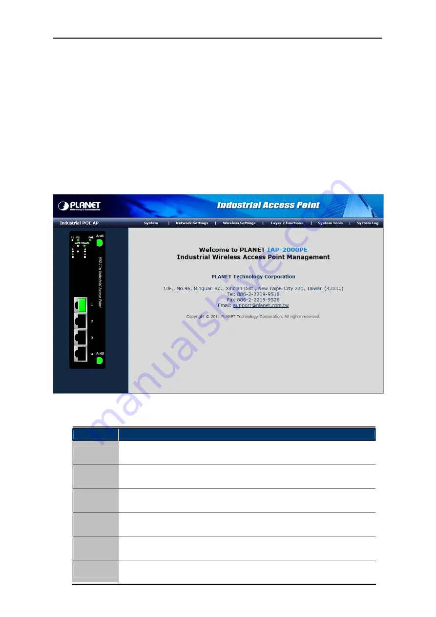
After a successful login, the main screen appears. The main screen displays the product name, the function menu, 
and the main information in the center. 


Figure 4-1 

Main Menu Screen 


Main Menu 

Description 

System 

This menu provides the system information and configuration of AP.


It will be 

explained in 

section 4.3

Network 

Settings 

This menu provides the configuration of LAN.


It will be explained in 

section 4.4

Wireless 

Settings 

This menu provides the configuration of wireless function.


It will be explained in 

section 4.5

Layer 2 

Functions 

This menu provides the port configuration. It will be explained in 

section 4.6

System 

Tools 

This menu provides the system tools of the AP.


It will be explained in 

section 4.7

System Log 

This menu provides the system log of the AP.


It will be explained in 

section 4.8

Summary of Contents for IAP-2000PE

Page 1: ......

Page 2: ...e limits are designed to provide reasonable protection against harmful interference in a residential installation This equipment generates uses and can radiate radio frequency energy and if not installed and used in accordance with the instructions may cause harmful interference to radio communications However there is no guarantee that interference will not occur in a particular installation If t...

Page 3: ...OUNCIL OF 9 March 1999 on radio equipment and telecommunication terminal Equipment and the mutual recognition of their conformity R TTE The R TTE Directive repeals and replaces in the directive 98 13 EEC Telecommunications Terminal Equipment and Satellite Earth Station Equipment As of April 8 2000 Safety This equipment is designed with the utmost care for the safety of those who install and use it...

Page 4: ...sult of the presence of hazardous substances in electrical and electronic equipment end users of electrical and electronic equipment should understand the meaning of the crossed out wheeled bin symbol Do not dispose of WEEE as unsorted municipal waste and have to collect such WEEE separately Revision User s Manual for PLANET Industrial 802 11n PoE Wireless Access Point Model IAP 2000PE IAP 2000PS ...

Page 5: ...SFP Transceiver IAP 2001PE Only 18 2 4 2 Removing the Module 19 Chapter 3 USER MANAGEMENT INTERFACE 21 3 1 Overview 21 3 2 Requirements 21 3 3 Management Method 21 3 3 1 Web Management 21 3 3 2 PLANET Smart Discovery Utility 23 Chapter 4 WEB CONFIGURATION 26 4 1 Main Menu 26 4 2 Web Panel 27 4 3 System 28 4 3 1 Operation Mode 28 4 3 2 Management 29 4 3 3 SNMP Configuration 30 4 3 4 Status 32 4 4 N...

Page 6: ...4 7 3 Upload Firmware 71 4 7 4 Settings Management 71 4 7 5 Reboot 72 4 7 6 Statistics 73 4 8 System Log 74 Chapter 5 PoE Power over Ethernet Overview 75 5 1 What is PoE 75 5 2 PoE Provision Process 77 Appendix A Networking Connection 79 A 1 DATA OUT PoE Switch RJ 45 Port Pin Assignments Port 1 to Port 4 79 A 2 10 100Mbps 10 100Base TX 79 ...

Page 7: ...ge PLANET IAP 200x Industrial AP x 1 5 dBi Antenna x 2 Quick Installation Guide x 1 CD ROM User s Manual included x 1 DIN Rail Kit x 1 Wall Mount Kit x 1 If any of these are missing or damaged please contact your dealer immediately if possible retain the carton including the original packing material and use them against to repack the product in case there is a need to return it to us for repair 1...

Page 8: ... WPS Button Reset Button Dimensions D x W x H 135mm x 87 8mm x 56mm Weight 871g Power Requirement DC 24V 48V DC 12 48V AC 24V Installation DIN Rail Kit and Wall Mount Ear Wireless Interface Specification Standard Compliance with IEEE 802 11b g n Frequency Band 2 4 to 2 4835GHz Industrial Scientific Medical Band Modulation Type DSS with DBPSK DQPSK QPSK and CCK OFDM with BPSK QPSK 16 QAM and 64 QAM...

Page 9: ...Virtual Server 802 1D 802 1Q VLAN QoS SNTP WMM DHCP Server Client IGMP Proxy and DNS Proxy UPnP and DDNS SNMP Management Web based configuration Standards Conformance Standards Compliance IEEE 802 11b g and 802 11n Wireless LAN IEEE 802 3 Ethernet IEEE 802 3u Fast Ethernet IEEE 802 3x Full Duplex Flow Control IEEE 802 3af Power over Ethernet IEEE 802 1Q VLAN Environment Specification Temperature H...

Page 10: ...nual of IAP 200x Series 9 Chapter 2 INSTALLATION 2 1 Hardware Description 2 1 1 Physical Dimension IAP 200x series Industrial Access Point dimension D x W x H 135mm x 87 8mm x 56mm Figure 2 1 IAP 200xPx diagram ...

Page 11: ... panels of Industrial Access Points Figure 2 2 IAP 2000PS Figure 2 3 IAP 2000PE Figure 2 4 IAP 2001PE Reset Button In the bottom of the front panel the reset button is designed for reset the Industrial Access Point to the factory default settings Figure 2 5 Reset button of IAP 200x series ...

Page 12: ...t indicates the power 1 has power P2 Green It indicates the power 2 has power PWR Green It indicates the machine is power on FAL Green It indicates either the power 1 or power 2 has no power Wireless LAN LED Color Function WPS Orange It indicates WPS is enabled WLAN Green It indicates the wireless LAN is enabled SEC Orange It indicates the wireless security encryption is enabled 10 100Base TX Port...

Page 13: ...trial access point and make connection to it Please read the following topics and perform the procedures in the order being presented To install your wireless access point on a desktop or shelf simply complete the following steps 2 2 1 Installation Steps 1 Unpack the package of Industrial Access Point 2 Check if the DIN Rail is screwed on the Industrial Access Point or not If the DIN Rail is not s...

Page 14: ...port RJ 45 port and another side of RJ 45 cable category 5 to the network device s Ethernet port RJ 45 port ex Switch PC or Server The UTP port RJ 45 LED on the Industrial access point will light up when the cable is connected with the network device Please refer to the LED Indicators section for LED light indication Make sure that the connected network devices support Auto MDI MDI X If it does no...

Page 15: ...User s Manual of IAP 200x Series 14 Step 1 Screw the DIN Rail on the Industrial Access Point Figure 2 8 Step 2 Lightly press the button of DIN Rail into the track Figure 2 9 ...

Page 16: ...tep 3 Check the DIN Rail is tightly on the track Figure 2 10 Please refer to the following procedures to remove the Industrial Access Point from the track Step 5 Lightly press the button of DIN Rail for remove it from the track Figure 2 11 ...

Page 17: ... 2 12 Step 3 Use the screwdriver to screw the wall mount plate on the Industrial Access Point Step 4 Use the hook holes at the corners of the wall mount plate to hang the Industrial Access Point Step 5 To remove the wall mount plate reverse the steps above 2 3 Wiring the Power Input The 6 contact terminal block connector on the top panel of the Industrial access point is used for two DC redundant ...

Page 18: ...V2 V2 Figure 2 13 The Top Panel of IAP 2000PE IAP 2001PE V1 V1 V2 V2 Figure 2 14 The Top Panel of IAP 2000PS 2 Tighten the wire clamp screws for preventing the wires from loosing 1 2 3 4 5 6 Power 1 Fault Power 2 Figure 2 15 The Terminal Block ...

Page 19: ...nnected device The IAP 2001PE has one 100Base FX SFP interface Optional Multi mode Single mode 100Base FX SFP module Cabling Each 10 100Base TX ports use RJ 45 sockets for connection of unshielded twisted pair cable UTP Port Type Cable Type Connector 10Base T Cat 3 4 5 2 pair RJ 45 100Base TX Cat 5 5e 6 UTP 2 pair RJ 45 Any Ethernet devices like Hubs PCs can connect to the Industrial Access Point ...

Page 20: ...r cable 1 Attach the duplex LC connector on the network cable into the SFP transceiver 2 Connect the other end of the cable to a device switches with SFP installed fiber NIC on a workstation or a Media Converter 3 Check the LNK ACT LED of the SFP slot of the switch converter Ensure that the SFP transceiver is operating correctly 4 Check the Link mode of the SFP port if the link failed Co works wit...

Page 21: ...eries 20 Figure 2 17 Pull Out the SFP transceiver Never pull out the module without pull the handle or the push bolts on the module Direct pull out the module with violent could damage the module and SFP module slot of the device ...

Page 22: ...ious device configuration and management activities including System Power over Ethernet Tools 3 2 Requirements Network cables Please use standard network UTP cables with RJ 45 connectors Subscriber PC installed with Ethernet NIC Network Card The operating system of subscriber PC that running Windows XP 2003 Vista Windows 7 MAC OS X Linux Fedora Ubuntu and any other platform compatible with TCP IP...

Page 23: ... If your PC obtains the IP address from other devices please manually configure the correct IP address as 192 168 1 xxx xxx is from 2 to 254 Login to the IAP 200x Series 1 Open the web browser and enter IP address http 192 168 1 1 the factory default IP address if you have not changed before to access the management interface 2 When the following window appears please enter the user name and passw...

Page 24: ... via web management interface If you need more detailed description of any function please refer to the following sections for further information Figure 3 4 The Function Label of the Web UI 3 3 2 PLANET Smart Discovery Utility For easily list the PLANET Industrial Access Point in your Ethernet environment the Planet Smart Discovery Utility from user s manual CD ROM is an ideal solution The follow...

Page 25: ...re 3 6 PLANET Smart Discovery Utility Screen 4 This utility shows all necessary information of the devices such as MAC address device name firmware version device IP subnet address Users can also assign new password IP subnet address and description for the devices 5 After the setup is completed click Update Device Update Multi or Update All button to take effect The meaning of the 3 buttons above...

Page 26: ...e can be found in Option tools bar as well 6 Click the Control Packet Force Broadcast function and it will assign new setting value to the switch under different IP subnet address 7 Click the Connect to Device button and the Web login window as Figure 3 2 will appear 8 Click Exit button to exit the Planet Smart Discovery Utility ...

Page 27: ... the product name the function menu and the main information in the center Figure 4 1 Main Menu Screen Main Menu Description System This menu provides the system information and configuration of AP It will be explained in section 4 3 Network Settings This menu provides the configuration of LAN It will be explained in section 4 4 Wireless Settings This menu provides the configuration of wireless fu...

Page 28: ...nel On the left of the web management page the active panel displays the link status of management port and PoE ports Figure 4 2 Left Side of the Main Menu Screen Light Indicators Please refer the section 2 1 3 to find the descriptions of each LED ...

Page 29: ...IAP 200x Series 28 4 3 System The submenus of System option is shown below Figure 4 3 4 3 1 Operation Mode Select the operation mode you want to use and then click Apply button to make the changes take effect Figure 4 4 ...

Page 30: ...allows that the wireless interface is treated as WAN port and the Ethernet ports are LAN ports 4 3 2 Management Users may configure administrator account and password NTP settings and dynamic DNS settings in the page Figure 4 5 System Management Screenshot Administrator Settings Object Description Account Enter the username of the administrator in the field Maximum length 16 characters ...

Page 31: ...NS provider you are allowed to set the following parameters Account Enter the username of DDNS provider in the field Password Enter the password of DDNS provider in the field DDNS Enter the domain name of your device Click Apply to make the configuration take effect Click Cancel to cancel the new configuration 4 3 3 SNMP Configuration The Simple Network Management Protocol SNMP is an application l...

Page 32: ...identification of the contact person for this managed node together with information on how to contact this person System Name An administratively assigned name for this managed node By convention this is the node s fully qualified domain name A domain name is a text string drawn from the alphabet A Za z digits 0 9 minus sign No space characters are permitted as part of a name The first character ...

Page 33: ...string to display MIB object information and to set MIB objects Trap Configuration Object Description Mode Indicates the SNMP trap mode operation Possible modes are Enabled Enable SNMP trap mode operation Disabled Disable SNMP trap mode operation Trap Community Enter the community string for the trap station Trap Destination Enter the IP address of the trap manager Click Apply to make the configur...

Page 34: ...stem Up Time The period of time the device has been operational Operation Mode Displays the current operation mode Displays the unique hardware address assigned by manufacturer default MAC Address RF Mode Displays the current wireless band SSID Displays the current SSID BSSID Displays the MAC address of the wireless interface Channel Displays the current channel setting ...

Page 35: ...ser s Manual of IAP 200x Series 34 4 4 Network Settings The submenus of Network Settings option is shown below Figure 4 8 4 4 1 LAN Users can configure the network settings and the parameters as you wish ...

Page 36: ...92 168 1 1 Subnet Mask Enter the subnet mask of LAN port The subnet mask is an address code that determines the size of the network Normally use 255 255 255 0 as the subnet mask Default Gateway The default gateway that you want to use Primary DNS Server The primary DNS server address that you want to use Secondary DNS Server The secondary DNS Server address that you want to use MAC Address MAC add...

Page 37: ... Enable Object Description Start IP Address The first IP address that DHCP server assigns Client with DHCP function set will be assigned an IP address from the range End IP Address The last IP address that DHCP server assigns Subnet Mask The subnet mask of dynamic IP Primary DNS Server The primary DNS server address Secondary DNS Server The secondary DNS Server address Default Gateway The default ...

Page 38: ...the active clients with their Hostname MAC address assigned IP address and time expired information Figure 4 10 DHCP Client List 4 4 3 IPv6 Configure the IPv6 management information on this page The current screen as the Figure 4 11 appears is used to show the active IPv6 configuration Figure 4 11 IPv6 Configuration The page includes the following fields Object Description Address Provide the IPv6...

Page 39: ...epresented as eight fields of up to four hexadecimal digits with a colon separates each field For example fe80 215 c5ff fe03 4dc7 The symbol is a special syntax that can be used as a shorthand way of representing multiple 16 bit groups of contiguous zeros but it can only appear once 4 5 Wireless Settings Users can configure the related settings of wireless function here The submenus of Wireless Se...

Page 40: ...Click Wireless ON button to turn on wireless RF radio Network Mode There are five modes 11b only 11g only 11n only 2 4G 11b g mixed mode 11b g n mixed mode Network Name SSID The service set identification SSID is a unique name to identify the router in the wireless LAN Wireless stations associating to the router must have the same SSID Enter a descriptive name Its length is up to 32 characters ...

Page 41: ...his function will turn off connection between clients with different MBSSID Example The client connected with BSSID 1 When enable this function it will not connect with BSSID 2 Only can access between clients with SSID 1 BSSID Basic Service Set Identifier This is the assigned MAC address of the station in the access point This unique identifier is in Hex format and can only be edited when Multi BS...

Page 42: ...Disable or Enable Aggregation MSDU A MSDU Select Disable or Enable Auto Block ACK Select Disable or Enable Decline BA Request Select Disable or Enable HT TxStream Select how many antenna you want to use for transmitting data HT RxStream Select how many antenna you want to use for receiving data Click Apply to make the configuration take effect Click Cancel to cancel the new configuration 4 5 2 Adv...

Page 43: ...ice as AP mode The default BG protection mode is Auto Beacon Interval The interval time range is between 20ms and 999ms for each beacon transmission Beacons are the packets sending by Access point to synchronize the wireless network The beacon interval is the time interval between beacons sending by this unit in AP or AP WDS operation The default value is 100ms Date Beacon Rate DTM The DTM range i...

Page 44: ...ake does not occur Because the data frames are fragmented before they reach the RTS size Tx Power The Tx Power range is between 1 and 100 In case of shortening the distance and the coverage of the wireless network input a smaller value to reduce the radio transmission power For example input 80 to apply 80 Tx power The default value is 100 Short Preamble It is a performance parameter for 802 11 b ...

Page 45: ...bject Description Multicast to Unicast Converter Enable or disable Multicast to Unicast Converter After enabling this function the transmission quality of the wireless multicast stream can be improved Click Apply to make the configuration take effect Click Cancel to cancel the new configuration The advanced wireless setting is only for advanced user For the common user do not change any setting in...

Page 46: ... options including Disable Allow and Reject You can choose Disable Allow or Reject Select Allow only the clients whose MAC address is listed can access the router Select Reject the clients whose MAC address is listed are denied to access the router Add a station MAC If you want to add a station MAC enter the MAC address of the wireless station that are allowed or denied access to your router in th...

Page 47: ...de to OPEN or SHARED please fill in the related configurations at below Figure 4 17 OPEN WEP Object Description Specify a Key number for effective Default Key When you select the encryption type as WEP please input 5 13 ASCII 10 or 26 HEX characters for WEP Key WEP Keys 1 4 ...

Page 48: ...lect TKIP AES or TKIPAES for WPA algorithms WPA Algorithms Pass phrase Set 8 bit to 64 bit key in ASCII characters You may select to select Passphrase alphanumeric format or Hexadecimal Digits in the A F a f and 0 9 range to be the Pre shared Key Key Renewal Interval Please fill in a number for Group Key Renewal interval time ...

Page 49: ...nterval time Key Renewal Interval Enter the RADIUS Server s IP Address provided by your ISP IP Address Port Enter the RADIUS Server s port number provided by your ISP The Default is 1812 Enter the password that the Wireless AP shares with the RADIUS Server Shared Secret Session Timeout Session timeout interval is for 802 1x re authentication setting Set to zero to disable 802 1x re authentication ...

Page 50: ...page includes the following fields Object Description Select TKIP AES or TKIPAES for WPA algorithms WPA Algorithms Pass phrase Set 8 bit to 64 bit key in ASCII characters You may select to select Passphrase alphanumeric format or Hexadecimal Digits in the A F a f and 0 9 range to be the Pre shared Key Key Renewal Interval Please fill in a number for Group Key Renewal interval time ...

Page 51: ...e fill in a number for Group Key Renewal interval time Key Renewal Interval Only valid in WPA2 security Set WPA2 PMKID cache timeout period after time out the cached key will be deleted PMK Cache Period unit is minute PMK Cache Period Pre Authentication Only valid in WPA2 security The most important features beyond WPA to become standardized through 802 11i WPA2 are Pre authentication which ...

Page 52: ...terval unit is second and must be larger than 60 IP Address Enter the RADIUS Server s IP Address provided by your ISP Port Enter the RADIUS Server s port number provided by your ISP The Default is 1812 Shared Secret Enter the password that the Wireless AP shares with the RADIUS Server Session Timeout Session timeout interval is for 802 1x re authentication setting Set to zero to disable 802 1x re ...

Page 53: ...User s Manual of IAP 200x Series 52 F 802 1X Figure 4 22 802 1X The page includes the following fields 802 1X WEP Object Description WEP Enable or Disable WEP encryption ...

Page 54: ...d between the external authentication server and the access point The key is not send over the network This key must be the same on the external authentication server and your router Session Timeout Set the time interval for session Enter the proper value in the field Idle Timeout Set the idle time interval Enter the proper value in the field In order to connect to the wireless AP successfully the...

Page 55: ...this page Figure 4 23 WPS Config Object Description You can enable or disable the WPS function in this field WPS WPS Summary It displays the WPS information such as WPS Current Status WPS Configured and WPS SSID Object Description Generate Generate a new PIN code for the IAP 2000 Reset OOB Reset to out of box OoB configuration ...

Page 56: ...pports Wi Fi Protected Setup WPS you can establish a wireless connection between wireless adapter and Router using either Push Button Configuration PBC method or PIN method To build a successful connection by WPS you should also do the corresponding configuration of the new device for WPS function meanwhile I By Push Button Configuration PBC If the wireless adapter supports Wi Fi Protected Setup a...

Page 57: ...f the Router Step 1 Choose PIN and enter the PIN code of the wireless adapter Figure 4 25 WPS PIN of Wireless adapter Please find the PIN code of the wireless adapter from the configuration utility of the WPS Step 2 For the configuration of the wireless adapter please choose the option that you want to enter PIN into the Router in the configuration utility of the WPS and click Next Method Two Ente...

Page 58: ...ter please choose the option that you want to enter the PIN of the AP in the configuration utility of the Wireless adapter and enter it into the field Then click Next Step 3 You will see the WPS Current Status is Configured when the new device has successfully connected to the network Figure 4 27 WPS Configured ...

Page 59: ... know the MAC address of the other AP and the other AP must have a WDS link back to the AP Dynamically assigned and rotated encryption key are not supported in a WDS connection This means that WPA and other dynamic key assignment technologies may not be used Only Static WEP keys may be used in a WDS connection including any STAs that are associated with a WDS repeating AP Enter the MAC address of ...

Page 60: ...lazy mode the wireless AP automatically connects to the WDS devices that use the same SSID channel encryption mode and the physical mode You do not need to manually enter other MAC addresses of the peer routers To configure the Lazy Mode do as follows Step 1 In the Wireless Distribution System WDS page set the WDS mode to be Lazy Mode Step 2 Set the entity model and encryption type to accord with ...

Page 61: ...ess coverage Meanwhile it can also decrease the working load of the AP that accesses the Internet In that case the wireless card does not directly communicate with the wireless device that accesses the Internet but it directly communicates with the wireless AP Step 1 In the Wireless Distribution System WDS page select the WDS mode to be Bridge Mode Step 2 Set the entity model and encryption type t...

Page 62: ...Settings page Figure 4 21 Step 2 In this page set the channel of the wireless router to accord with the peer AP Step 3 In the Wireless Distribution System WDS page set the WDS mode to Repeater Mode set the Phy mode encryption type and Encryption key to accord with the peer router Then enter the MAC address of the peer AP After finishing the settings click the Apply button to save the settings The ...

Page 63: ...User s Manual of IAP 200x Series 62 Figure 4 22 Step 4 Choose Wireless Settings Security to display the Wireless Security Settings page ...

Page 64: ...Step 5 In this page set the security mode of IAP 2000 to accord with the peer router 4 5 6 Station List The administrator can check the users connected to the IAP 2000 in this page Figure 4 24 Click Refresh button to renew the list above immediately ...

Page 65: ...onfigure the port setting and VLAN in this page The submenus of Layer 2 Functions is shown below Figure 4 25 4 6 1 Port Status Users can check the information of the connection on each port in this page Figure 4 26 Click Refresh button to renew the list above immediately ...

Page 66: ... row Mode You can select Auto Negotiation 100 Full 100 Half 10 Full and 10 Half Flow Control You can choose Enable or Disable Port Enable You can choose Enable or Disable Click Apply to make the configuration take effect Click Cancel to cancel the new configuration 4 6 3 VLAN Setting Setting up Virtual LAN on the IAP 2000 increases the efficiency of the network by dividing the LAN into logical seg...

Page 67: ...N Member Configuration Object Description VLAN Group You can select enable or disable VID Set the VID here for each Virtual LAN Port 1 4 It means the LAN port on the IAP 2000 You can set the PVID for each port here PVID Port Priority You can decide the priority of each port here Click Apply to make the configuration take effect Click Cancel to cancel the new configuration ...

Page 68: ...e It shows the MAC address for each port here Figure 4 29 Click Refresh button to renew the list above immediately 4 7 System Tools Users can configure the related settings of IAP 2000 system here The submenus of System Tools option is shown below Figure 4 30 ...

Page 69: ...t any where with no hesitation 10 12 watts IP Surveillance Enterprise Museum Campus Hospital Bank can install IP Camera without limits of install location no need electrician to install AC sockets 3 12 watts PoE Splitter PoE Splitter split the PoE 48V DC over the Ethernet cable into 5 9 12V DC power output It frees the device deployment from restrictions due to power outlet locations which elimina...

Page 70: ...o provide power for the PDs Power Budget Show the total watts usage of PoE ports PoE Function Enable or disable the PoE function of each port Priority Set port priority for the POE power management It can choose the port priority value is 1 4 High priority is 1 Device Class Class 0 is the default for PDs However to improve power management at the PSE the PD may opt to provide a signature for Class...

Page 71: ... be less than the Power Reservation value Once power overload detected the port will auto shut down and keep on detection mode until PD s power consumption lower than the power limit value 4 7 2 IPv6 Ping This page allows you to issue ICMPv6 PING packets to troubleshoot IPv6 connectivity issues After you press the Test button 5 ICMPv6 packets are transmitted and the sequence number and roundtrip t...

Page 72: ...you may upgrade the correct new version firmware to obtain new functionality Figure 4 31 Update Firmware Location Click Browse to select the firmware file and click Apply to upgrade the firmware If the firmware is uploaded in an improper way the system would core dump 4 7 4 Settings Management You may save system settings by exporting them to a configuration file restore them by importing the file...

Page 73: ...e location Click Browse to select the configuration file and then click Import to upload the configuration file Click Cancel to cancel the uploading operation Load Factory Defaults Load Default Button Click Load Default to make AP return to the default settings 4 7 5 Reboot The Reboot screen allows you to restart your AP with its current settings ...

Page 74: ...200x Series 73 Figure 4 33 Click the Reboot button and the device will restart 4 7 6 Statistics It displays the information about AP status including system information Internet configurations and local network Figure 4 34 ...

Page 75: ...system log dialog allows you to view the system log and click the Refresh button to fresh the system event logs You are allowed to view and disable enable the system log in this page Figure 4 35 Click Refresh to refresh the log Click Clear to clear the log ...

Page 76: ...t End Span End Span device is direct connecting with power device End Span could also tap the wire 1 2 and 3 6 PoE System Architecture The specification of PoE typically requires two devices the Powered Source Equipment PSE and the Powered Device PD The PSE is either an End Span or a Mid Span while the PD is a PoE enabled terminal such as IP Phones Wireless LAN etc Power can be delivered over data...

Page 77: ...s when your company moves into new offices next month The company staff has been clamoring for a wireless access point in the picnic area behind the building so they can work on their laptops through lunch but the cost of electrical power to the outside is not affordable Management asks for IP Surveillance Cameras and business access systems throughout the facility but they would rather avoid anot...

Page 78: ...tor indicates 14 5 20 5 12 5 25 0 Startup Where the powered device will startup 42 38 Normal operation Supply power to device 36 57 25 0 60 0 1 Line Detection Before power is applied safety dictates that it must first be ensured that a valid PD is connected to the PSE s output This process is referred to as line detection and involves the PSE seeking a specific 25 KΩ signature resistor Detection o...

Page 79: ...me following disconnection of a PD from an active port When a PD is disconnected there is a danger that it will be replaced by a non PoE ready device while power is still on Imagine disconnecting a powered IP phone utilizing 48 VDC then inadvertently plugging the powered Ethernet cable into a non PoE notebook computer What s sure to follow is not a pretty picture The standard defines two means of ...

Page 80: ...other switch a bridge or a hub a straight or crossover cable is necessary Each port of the Switch supports auto MDI MDI X detection That means you can directly connect the Switch to any Ethernet devices without making a crossover cable The following table and diagram show the standard RJ 45 receptacle connector and their pin assignments RJ 45 Connector pin assignment Contact MDI Media Dependant In...

Page 81: ...White Green 4 Blue 5 White Blue 6 Green 7 White Brown 8 Brown 1 White Orange 2 Orange 3 White Green 4 Blue 5 White Blue 6 Green 7 White Brown SIDE 2 8 Brown Straight Cable SIDE 1 SIDE2 SIDE 1 1 2 3 4 5 6 7 8 1 2 3 4 5 6 7 8 1 White Orange 2 Orange 3 White Green 4 Blue 5 White Blue 6 Green 7 White Brown 8 Brown 1 White Green 2 Green 3 White Orange 4 Blue 5 White Blue 6 Orange 7 White Brown SIDE 2 8...

Page 82: ...n Wireless AP spełnia wszystkie istotne wymogi i klauzule zawarte w dokumencie Directive 1999 5 EC Ελληνικά ΜΕ ΤΗΝ ΠΑΡΟΥΣΑ PLANET Technology Corporation ΔΗΛΩΝΕΙ ΟΤΙ ΑΥΤΟ Industrial 802 11n Wireless AP ΣΥΜΜΟΡΦΩΝΕΤΑΙ ΠΡΟΣ ΤΙΣ ΟΥΣΙΩΔΕΙΣ ΑΠΑΙΤΗΣΕΙΣ ΚΑΙ ΤΙΣ ΛΟΙΠΕΣ ΣΧΕΤΙΚΕΣ ΔΙΑΤΑΞΕΙΣ ΤΗΣ ΟΔΗΓΙΑΣ 1999 5 ΕΚ Português PLANET Technology Corporation declara que este Industrial 802 11n Wireless AP está confor...

Reviews: