


Adjusting Input Levels
34
m70L Installation & Configuration Guide
Adjusting Levels for Digital Sources
Caution:
These controls are advanced level controls and should not be adjusted unless you
have been instructed by the factory or are familiar with black level adjustments.
Digital computer sources do not normally need adjustment, but the controls are
there if you need them. They are used to correct the digital blacks that come from
video cards that have incorrect levels.
1
Select a source in the
PICTURE
menu.
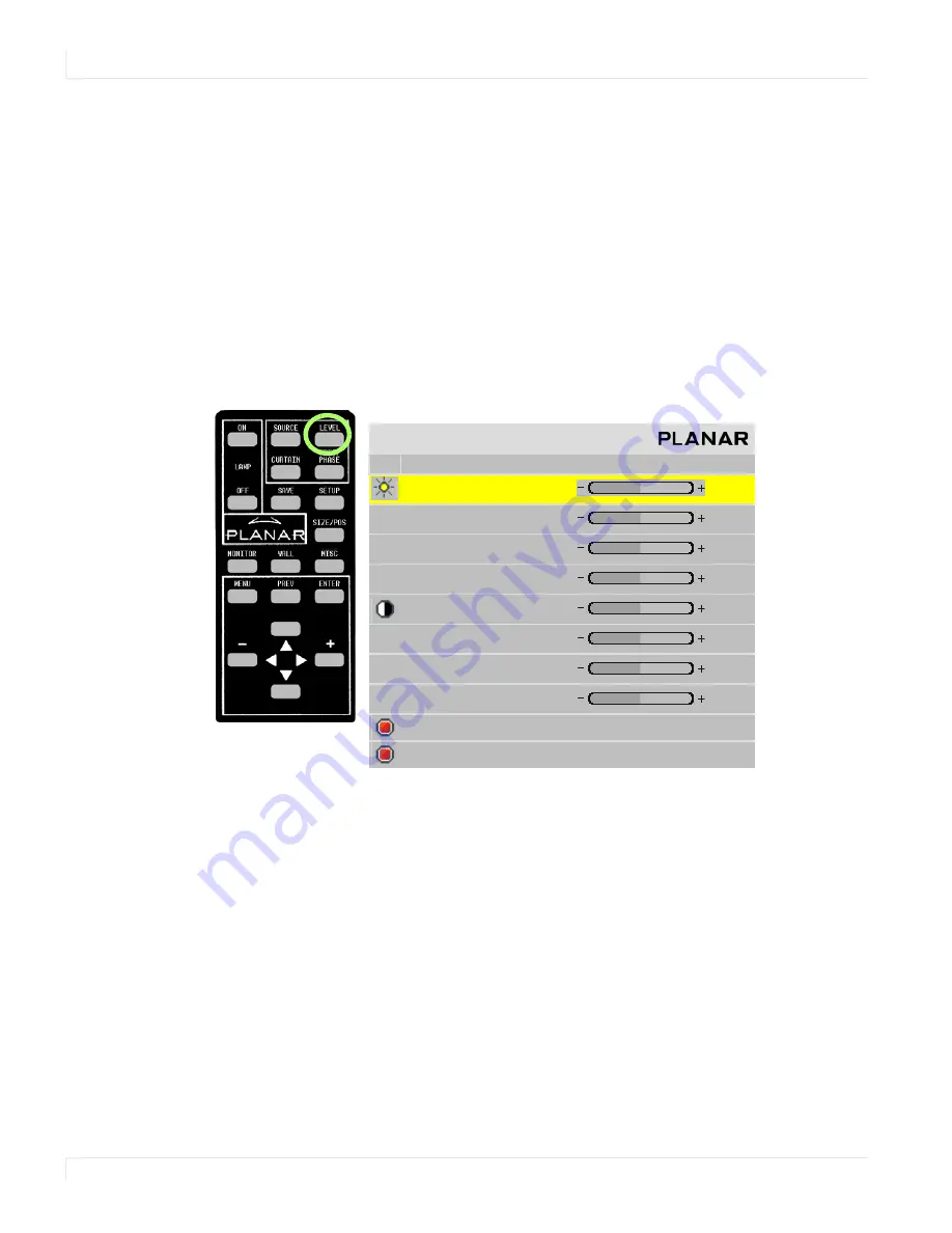
2
To view the
INPUT
LEVELS
menu, press
LEVEL
on the remote. (The
INPUT
LEVELS
menu looks different for different colorspaces. The
INPUT
LEVELS
menu for Digital
RGB sources is shown below).
3
If you have changed black and white levels, select the
SET
TO
NOMINAL
FOR
RGB
LEVELS
line to change them back to the default. This is the default for most
sources.
4
It would be rare for you to adjust black and white levels for a digital source.
However, depending on the source, what black and white “mean” can be
different. In most cases, black will be 0 and white will be 255. However, for some
sources, such as DVD players, black can be 16 and white can be 235. If this is the
case, select the
SET
TO
NOMINAL
FOR
VIDEO
LEVELS
line and press
ENTER
.
This
will change the black and white levels to the required values to correctly display
the range of colors in the display.
5
Although it is not required, we recommend that you save the configuration to a
memory slot. (See "Saving Configurations" on page 74.)
I n p u t L e v e l s
C e n t e r P o i n t
2 5 5
2 5 5
2 5 5
B l a c k L e v e l ( o f f s e t ) A l l
1 2 8
R e d
1 2 8
G r e e n
1 2 8
B l u e
1 2 8
W h i t e L e v e l ( g a i n ) - A l l
1 3 2
R e d
1 2 0
G r e e n
1 5 4
B l u e
1 2 2
S e t t o N o m i n a l f o r R G B L e v e l s ( 0 - 2 5 5 )
S e t t o N o m i n a l f o r Vi d e o L e v e l s ( 1 6 - 2 3 5 )
Summary of Contents for m70L
Page 1: ...m70L Installation Guide ...
Page 2: ......
Page 4: ...4 m70L Installation Guide ...
Page 18: ...Before You Begin 10 m70L Installation Configuration Guide ...
Page 24: ...Installing the Video Input Module VIM 16 m70L Installation Configuration Guide ...
Page 28: ...Connecting Power 20 m70L Installation Configuration Guide ...
Page 52: ...Adjusting Sharpness 44 m70L Installation Configuration Guide ...
Page 54: ...Adjusting Position 46 m70L Installation Configuration Guide ...
Page 56: ...Viewport 48 m70L Installation Configuration Guide ...
Page 60: ...Adjusting Color Balance 52 m70L Installation Configuration Guide ...
Page 74: ...Backlight Control 66 m70L Installation Configuration Guide ...
Page 78: ...Serial Port Settings and Diagnostics 70 m70L Installation Configuration Guide ...
Page 88: ...Saving and Recalling Configurations 80 m70L Installation Configuration Guide ...
Page 100: ...92 m70L Installation Configuration Guide ...
Page 102: ...Rear View 94 m70L Installation Configuration Guide Rear View ...


