background image


  7 


Rele

asing

 the


Opt

ical Engin

e

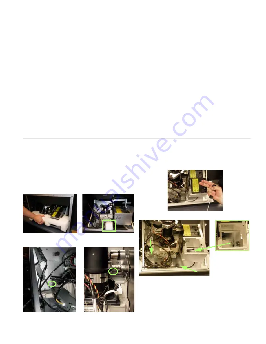
Releasing the Optical Engine

The c50R/c67R is shipped with the optical engine in a locked-
down position. You must release it and put it in the operation 
position before you can align the image to the screen. You nor-
mally do this 

before

 you install the c50R/c67R in a wall. 

1 From the rear, remove the back panel.
2 Remove the shipping foam from the back of the unit; the 

large piece first and then the small wedge.

3 Using a Phillips #2 screwdriver, remove two M4 x 16mm 

keystone screws and washers.

4 To gain access to the area below the rear lamp, remove the 

lamp. 

5 Remove three M4 x 8mm screws and fender washers.

6 Replace the rear lamp.
7 Replace the back panel.

Summary of Contents for c50RP

Page 1: ...ne 1 503 748 5799 Toll free Phone 1 866 PLANAR1 752 6271 Email planarsupport planar com Contents 1 Product Safety Information 2 Planning for Your Installation 3 Checking Accessories 4 Installing the O...

Page 2: ...our physical health and safety are important Take a few minutes to read this section at least once Note The plug on the power cord serves as the disconnect for this product No user serviceable parts a...

Page 3: ...ation Configuration Guide CD Have the following tools available String to check the straightness across the fronts of the units Long carpenter s level 48 or longer if possible Steel tape measure to ch...

Page 4: ...in a separate accessory kit Bottom Row Screen Support If you have a wall higher than two units this support provides additional wall stability Brackets The following brackets are available Center Scre...

Page 5: ...off the power on the c50R c67R and remove the power cord WARNING Always turn off power and remove the power cord when adding or removing an electronic part 3 Remove the two screws and the small plate...

Page 6: ...te may be stuck to some EMI tape Try not to tear the tape 7 Remove the cover of the control board It is a snug fit Installing the VIM 1 Slide the VIM in its space and press it into its connector on th...

Page 7: ...here will multiply as the wall goes up Installing the Second and Subsequent Rows 1 Unpack only the displays that will be in this row page 2 2 Make sure all VIMs and Option keys are installed on each...

Page 8: ...r mally do this before you install the c50R c67R in a wall 1 From the rear remove the back panel 2 Remove the shipping foam from the back of the unit the large piece first and then the small wedge 3 U...

Page 9: ...a time with one person holding still and the other person hanging the screen on the hook 6 Press the heel of your hand against all four corners of the screen until the spring loaded latches click int...

Page 10: ...ts does change what comes out of it The selected picture from either Analog In or Digital In always comes out the Digital Out connector in digital form Note The Digital Out signal does not strictly co...

Page 11: ...e Power Supply Most UPS devices will work with the c50R c67R Review the power specifications of your UPS device to make sure it is compatible with the c50R c67R Turning Power On Off 1 With the power c...

Page 12: ...tions See explanations next to the remote control pic ture on this page for additional navigation information Some of the setups described in this Quick Start Guide will explain how to navigate throug...

Page 13: ...press ENTER The PIC TURE menu changes to display the settings for that source When the Source is Familiar to c50R c67R When a new source is selected the c50R c67R looks through a list of the last 10...

Page 14: ...isplay an all white picture from the source computer 5 In the INPUT LEVELS menu select AUTO WHITE LEVEL and press ENTER Wait for Working to disappear 6 The c50R c67R is now adjusted to the black and w...

Page 15: ...Generation Equip ment you can use it to adjust bright ness Pluge is used to calibrate the black level on a video monitor 7 Although it s not required it is recommended that you save the configura tion...

Page 16: ...s use the internal Test Patterns for color balancing not an external pattern 4 When all displays are white find the least bright display in the array This will be the baseline display and you will not...

Page 17: ...solid color contact Pla nar s Technical Support Department The source absent pane is not visible The source is displaying a solid color or a test pattern 4 Ensure the power cable is con nected and th...

Page 18: ...amp remove the three thumb screws and bracket above the lamps 6 Loosen the three captive thumb screws on top of the lamp 7 Lift the wire handle and pull the lamp straight up and out 8 The picture see...

Page 19: ...1 Using the remote turn off the lamp and allow the cooling fans to stop about one minute before proceeding 2 Remove the front screen 3 Loosen the captive screws at the top and bottom of the control b...

Page 20: ...ical Construction File required by this Directive is maintained at the corporate headquarters of Planar Systems Inc 1195 NW Compton Drive Beaverton OR 97006 Note This equipment has been tested and fou...

Reviews: