background image


14


Ad
justi

ng Inpu

t

Le
ve

ls & P

o

sition

Adjusting Input Levels and Position

Adjusting Levels for Video Sources

Video sources are adjusted best if a color bar test pattern is 
available from the video source: the DVD or VCR player. If not, 
you will have to adjust by eye and the “feel” of the picture.

Note: 

When a video source is selected, Auto Setup Options are not 

available. Adjustments must be made manually.

Adjusting the Picture

1 Select a video source in the 

PICTURE

 menu.

2 Press 

LEVEL

 on the remote to open 

INPUT


LEVELS

.

3 Adjust one of the following:

Any picture from the video source. 

Using a standard SMPTE color bar pattern from the source.

Adjusting With Color Bars

1 If possible, use a SMPTE color bar pattern from the video 

source you will use for the program material.

2 In  the 

INPUT


LEVELS

 menu, check 

BLUE


ONLY

. You should 

see the alternate color bars, all of them blue.

3 Adjust 

SATURATION

 to make the outer two color bars 

match. Match them in brightness; they will already match 
in color.

4 Adjust 

HUE

 to make the inner two color bars match.

5 Uncheck 

BLUE


ONLY

.

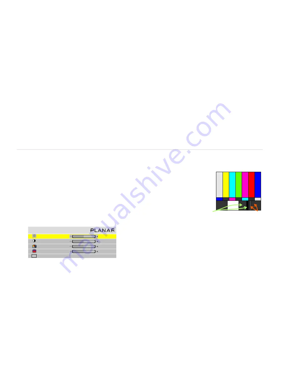
6 If the color bar pat-

tern has a pluge 
(Picture Line-Up 
Generation Equip-
ment), you can use 
it to adjust bright-
ness. Pluge is used 
to calibrate the 
black level on a 
video monitor.

7 Although it’s not 

required, it is recommended that you save the configura-
tion to a memory slot. See the Installation & Configuration 
Guide for more information about saving memory slots.

Adjusting Position

Position moves the picture on the screen but does not move the 
menus. Press 

SIZE

/

POS

 on the remote once to open the 

PICTURE


POSITION

 menu. The four arrow keys move the picture on the 

screen.

The numbers for Horizontal and Vertical Position refer to the 
number of pixels from sync to the first displayed pixel. These 
numbers get smaller as the picture moves up and to the left.

The Horizontal Position number shows the number of pixels 
from the beginning of H sync to the first active pixel. Because 
there are many black pixels after H sync, this number will not be 
zero when the picture is at the left border of the screen.

The Vertical Position number is the number of lines from V sync 
to the first active line, so it will not be zero when the picture is at 
the top of the screen.

I n p u t   L e v e l s

B r i g h t n e s s

1 4 0

C o n t r a s t

1 6 5

S a t u r a t i o n

1 5 0

H u e

1 2 8

B l u e   O n l y

Adjust 
brightness so 
you can’t see 
the 
difference 
between 
these two 
marks

But you can you 

can


see the difference 
between these two 
marks

Summary of Contents for c50RP

Page 1: ...ne 1 503 748 5799 Toll free Phone 1 866 PLANAR1 752 6271 Email planarsupport planar com Contents 1 Product Safety Information 2 Planning for Your Installation 3 Checking Accessories 4 Installing the O...

Page 2: ...our physical health and safety are important Take a few minutes to read this section at least once Note The plug on the power cord serves as the disconnect for this product No user serviceable parts a...

Page 3: ...ation Configuration Guide CD Have the following tools available String to check the straightness across the fronts of the units Long carpenter s level 48 or longer if possible Steel tape measure to ch...

Page 4: ...in a separate accessory kit Bottom Row Screen Support If you have a wall higher than two units this support provides additional wall stability Brackets The following brackets are available Center Scre...

Page 5: ...off the power on the c50R c67R and remove the power cord WARNING Always turn off power and remove the power cord when adding or removing an electronic part 3 Remove the two screws and the small plate...

Page 6: ...te may be stuck to some EMI tape Try not to tear the tape 7 Remove the cover of the control board It is a snug fit Installing the VIM 1 Slide the VIM in its space and press it into its connector on th...

Page 7: ...here will multiply as the wall goes up Installing the Second and Subsequent Rows 1 Unpack only the displays that will be in this row page 2 2 Make sure all VIMs and Option keys are installed on each...

Page 8: ...r mally do this before you install the c50R c67R in a wall 1 From the rear remove the back panel 2 Remove the shipping foam from the back of the unit the large piece first and then the small wedge 3 U...

Page 9: ...a time with one person holding still and the other person hanging the screen on the hook 6 Press the heel of your hand against all four corners of the screen until the spring loaded latches click int...

Page 10: ...ts does change what comes out of it The selected picture from either Analog In or Digital In always comes out the Digital Out connector in digital form Note The Digital Out signal does not strictly co...

Page 11: ...e Power Supply Most UPS devices will work with the c50R c67R Review the power specifications of your UPS device to make sure it is compatible with the c50R c67R Turning Power On Off 1 With the power c...

Page 12: ...tions See explanations next to the remote control pic ture on this page for additional navigation information Some of the setups described in this Quick Start Guide will explain how to navigate throug...

Page 13: ...press ENTER The PIC TURE menu changes to display the settings for that source When the Source is Familiar to c50R c67R When a new source is selected the c50R c67R looks through a list of the last 10...

Page 14: ...isplay an all white picture from the source computer 5 In the INPUT LEVELS menu select AUTO WHITE LEVEL and press ENTER Wait for Working to disappear 6 The c50R c67R is now adjusted to the black and w...

Page 15: ...Generation Equip ment you can use it to adjust bright ness Pluge is used to calibrate the black level on a video monitor 7 Although it s not required it is recommended that you save the configura tion...

Page 16: ...s use the internal Test Patterns for color balancing not an external pattern 4 When all displays are white find the least bright display in the array This will be the baseline display and you will not...

Page 17: ...solid color contact Pla nar s Technical Support Department The source absent pane is not visible The source is displaying a solid color or a test pattern 4 Ensure the power cable is con nected and th...

Page 18: ...amp remove the three thumb screws and bracket above the lamps 6 Loosen the three captive thumb screws on top of the lamp 7 Lift the wire handle and pull the lamp straight up and out 8 The picture see...

Page 19: ...1 Using the remote turn off the lamp and allow the cooling fans to stop about one minute before proceeding 2 Remove the front screen 3 Loosen the captive screws at the top and bottom of the control b...

Page 20: ...ical Construction File required by this Directive is maintained at the corporate headquarters of Planar Systems Inc 1195 NW Compton Drive Beaverton OR 97006 Note This equipment has been tested and fou...

Reviews: