5
In
st
all
ing
the
VI
M
Installing the Video Input Module (VIM)
The optional VIM is shipped separately and installed on site.
WARNING!
Always turn off power and remove the power cord when
adding or removing an electronic part.
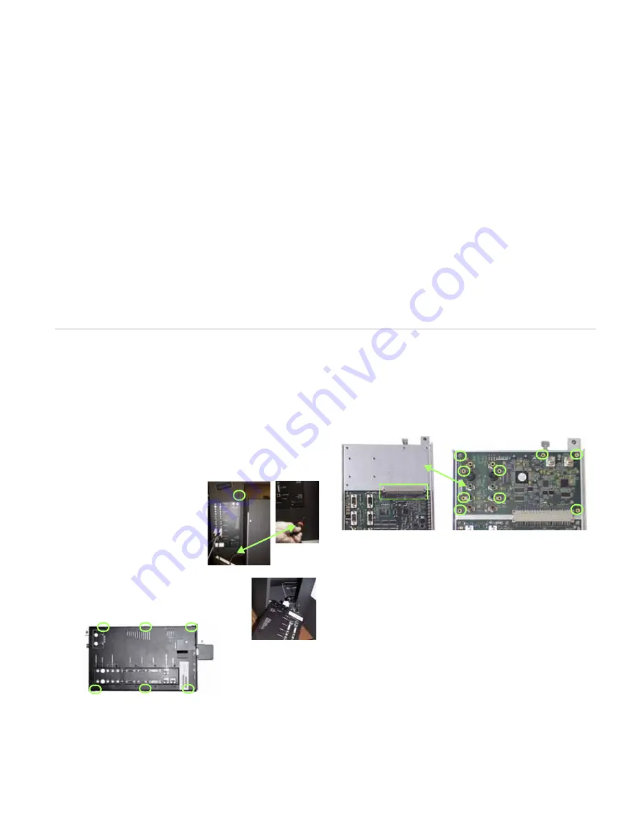
Removing the Control Board
1 Attach a ground strap to your wrist and the chassis.
WARNING!
Failure to properly use a grounding strap can destroy sensi-
tive electronic components in the control board.
2 Loosen the screws on the
back of the display that hold
the control board in place.
3 Swing the control board to
about 45° and lift it off its pin
hinges. It will still be con-
nected to two or more
cables at the bottom.
4 Bring the control board partly out the
opening and disconnect all the cables.
5 Remove six screws from the sides of the
covers.
6 Remove the DVI connector EMI shield. Use a 3/16" nut
driver. The EMI plate may be stuck to some EMI tape. Try
not to tear the tape.
7 Remove the cover of the control board. It is a snug fit.
Installing the VIM
1 Slide the VIM in its space and press it into its connector on
the main control board.
2 Install nine screws to secure the board.
3 Replace the control board cover. Check first to see that all
the LEDs are straight and none are bent over. Carefully lay
the cover all the way down over the control board, watch-
ing the LEDs to see that they are visible through their
holes.
4 Press the cover onto the control board; it is a snug fit.
5 Attach the cover using the 6 screws at the sides.
6 Install the two nuts and washers in the top right corner.
7 Replace the EMI shield at the bottom with the 3/16" stand-
off nuts.
8 Reconnect any cables you may have removed.
9 Replace the control board in the display. The hinge is two
pins on the display chassis and two holes on the control
board. Fit the top hole first. That pin is a little longer.
10 It is now safe to replace the power cord and turn on the
power.
Connector


