6.1 UNIT DISASSEMBLY
1. Open the dust cover and remove the rubber sheet and
turntable.
2. Close the dust cover and gently turn the unit over.
Place the unit on something soft that won't scratch the
dust cover.
3. Removing screw O releases the under base.
4. Removing screw f) releases the motor assembly.
5. Removing screw@ releases the control board unit.
6. Removing screw 8 releases the SW board unit,
and removing screw0releases the PU board unit.
7. To remove the dust cover, open it up and remove the
plastic rivets labeled
0
.
(The plastic rivets can be re
moved easily by pushing the pins from the inside of the
dust cover.)
8. Removing screwfjwill release the mechanism base unit.
Mechanism base
board assembly
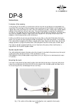
6.2 CARRIAGE REMOVAL
1. Remove the fixer from the carriage and the wire from
the pulley. (See Figure 6.2)
2. Remove screw fl)and pull the guide bar away from the
carriage in the direction indicated by the arrow. The
carriage and tonearm assembly can now be removed.
3. Removing the spring will release the carriage board as
sembly, and removing screw
0
will release the mech
anism base board assembly.
Wire
�Fixer
�
Pulley
Fig. 6-2 Removing Carriage Wire
Carriage board
assembly
Fig. 6-3 Carriage Removal
18