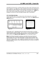
SWITCH 2
This switch bank is set through the
Function Switch Setting Mode
and the settings
are stored in Register D.
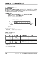
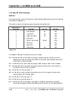
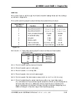
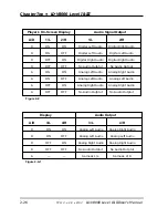
This switch sets the player’s serial interface characteristics as follows :
Bit 0 & Bit 1: These bits set the player’s serial interface communication
speed as follows:
Bit 2: This bit selects parity enable or disable.
Bit 3: This bit selects even or odd parity.
Bit 4: This bit selects 1 or 2 stop bits.
Bit 5: This bit selects 7-bit or 8-bit data length.
Bit 6: This bit selects the termination code (<C/R> & <L/F> or <C/R> only).
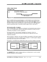
Bit 7: This bit establishes the serial interface as either an input data device
or a controller during Level II program execution. When a Level II program is
not executed, there is no difference. When Input Device is selected, the
player recognizes only ASCII 0 through 9 (Input Command Response) and
ASCII A through J (Function Input Command Response).
LD-V8000 Level I & III • Chapter Two
LD-V8000 Level I & III User’s Manual
TP 113
v. 2.1 • 2/93
2-19
Function
On (=1)
Off (=0)
0
Baud Rate Switch 0
1
Baud Rate Switch 1
2
Parity Enable/Disable
Enable
Disable
3
Even/Odd Parity
Odd
Even
4
Stop Bit
2 bits
1 bit
5
Data Length
7 bits
8 bits
6
TxD Terminator
<C/R> & <L/F>
<C/R>
7
Serial Port Setting
Input Device
Controller
Switch Number 2
Bit Position
See Figure 2-R, below
See Figure 2-R, below
See Figure 2-R, below
See Figure 2-R, below
Figure 2-Q
Switch 1
Switch 0
Baud Rate
Off Off
9600
bps
Off
On
4800 bps
On
Off
1200 bps
Figure 2-R

