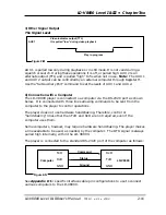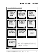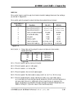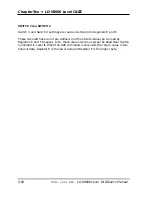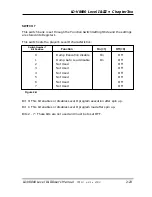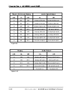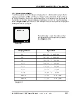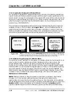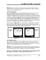
Pages P-8 through P-11 allow you to set switches 3 and 4. These
switches can be set by the user and used to identify a particular
player or store other information They are not necessary for most
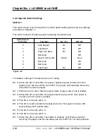
normal player operation. Page P-12 contains a summary of the seven
switch settings. This chart reflects the parameters selected in the
previous pages.
Initialization; Exiting Switch Setting Mode
When all your switches have been set, press DISPLAY. This does two
things. It saves the settings you have selected to the player’s
memory, and it exits
Function Switch Setting Mode
, returning the
player to
Normal Control Mode
.
NOTE:
Turning OFF the player before the DISPLAY button is pressed
will ignore any changes made and the player will default to the
previous settings. Pressing the OPEN/CLOSE Button returns all
settings to their defaults.
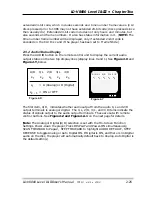
3. Setting the Baud Rate Using The Player’s Front Panel Buttons
Enter
Function Switch Setting Mode
by pressing Power-ON and the DISPLAY
button simultaneously. Press SCAN FORWARD to move through the on-
screen “pages” to page five. The top of page five reads “RS-232 Switch P-5”.
You will see the following functions listed:
* BAUD RATE (9600 is the default setting; other options are 4800 and 1200.)
* PARITY (No Parity is the default setting; other options are EVEN or ODD.)
* STOP BIT (1 Stop Bit is the default setting; the other option is 2 Stop Bits.)
* DATA LENGTH (8 Bit is the default setting; the other option is 7 Bit.)
Press the STEP FORWARD button to highlight the specific function you wish
to change (ie. BAUD RATE, PARITY, STOP BIT, or DATA LENGTH). Then
press the STEP REVERSE Button to toggle through and select the correct
setting, as indicated by software you may be using with the player. Press the
DISPLAY button to commit the settings to the player’s memory and to exit
Function Switch Setting Mode
, returning the Player to
Normal Control Mode
.
Follow the general steps described in Sub-Point 2
(Setting Switches)
of this
section to change the settings of any of the On-Screen Function Switches
included on Pages P-2 to P-7.
Chapter Two • LD-V8000 Level I & III
2-14
TP 113 v. 2.0 • 2/93
LD-V8000 Level I & III User’s Manual


