background image

61

Basic Operation

BASIC

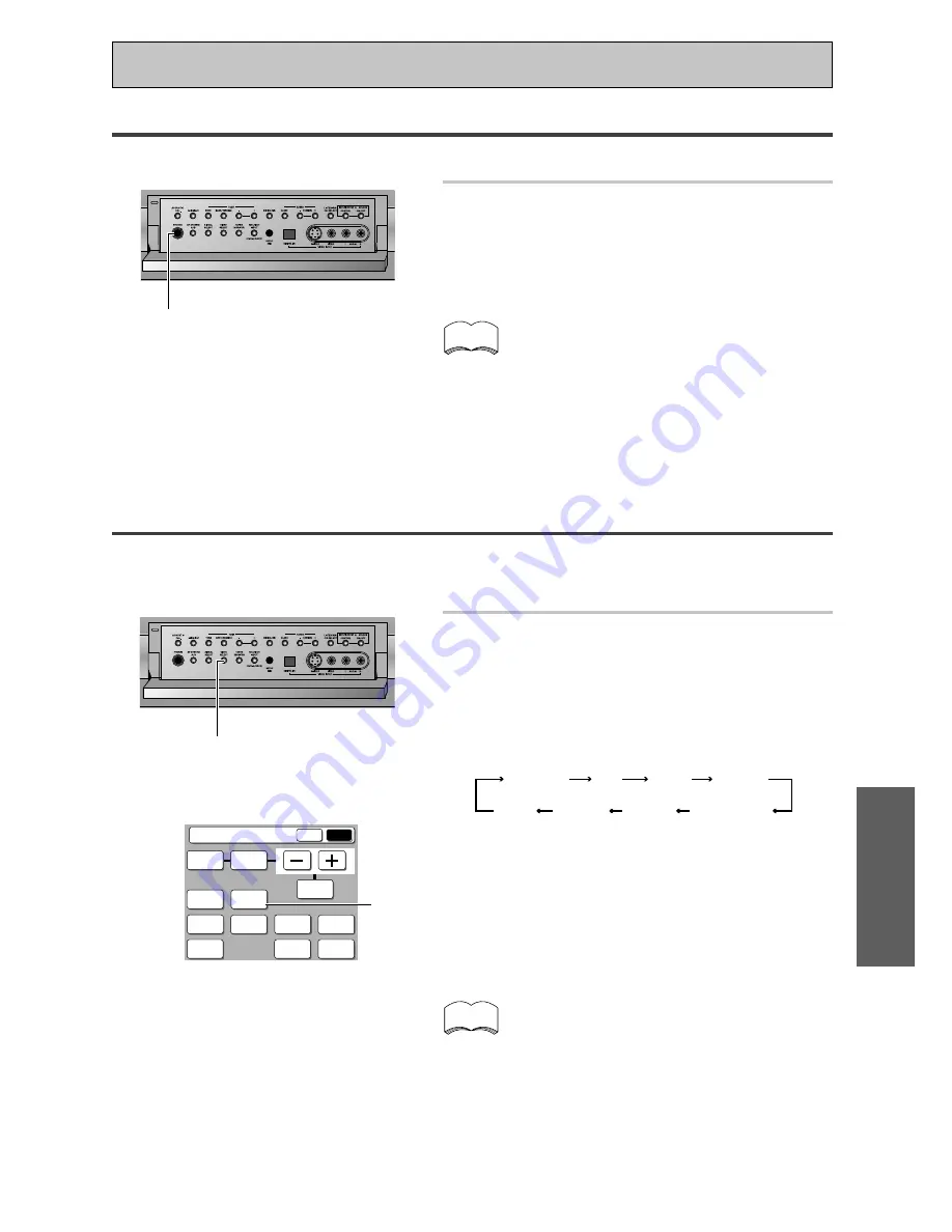
Video Select

This function allows you to listen to one sound source while you watch a different video source on your TV. The
sound source is set in the normal fashion as is explained on p.49 & 50. You then alter the video input with the
VIDEO SELECT button.

1

Use the VIDEO SELECT button on the
RECEIVER’S sub screen or the front
panel to cycle through the different
possible video inputs.

The first press shows the video input you are currently
using. After that pressing VIDEO SELECT cycles though
the possibilities in the following order:

The OFF setting means you are listening without a
video signal. (Also, when you select CD-R/TAPE1/MD,
CD, TUNER, or PHONO functions the VIDEO SELECT
will be set to off.)

After choosing a video input the display on the receiver
will show that input for about 5 seconds and then
revert to showing the listening mode the receiver is in.

 VIDEO SELECT

• The VIDEO SELECT remains set to the input you

chose until you change the audio input.

• If you change audio functions the receiver will

reset itself to make the video and audio inputs
correspond.
Also, if you switch the power of the receiver off
when you turn it back on the video and audio in-
puts will reset so that they correspond. The same
thing will happen if you select CD-R/TAPE1/MD,
CD, TUNER, or PHONO functions.

memo

Using the Headphones

The headphone feature is explained here.

1

Plug headphones into the Phones
jack on the front of the receiver.

No sound will be audible from the speakers when
headphones are plugged in.

• All listening modes will be downmixed to 2 chan-

nels.

• If you’re listening to a 2 channel source there will

be no matrix decoding (i.e. you will not be able to
get surround sound decoding).

• If your U-shaped connectors (see p.34) aren’t in

place you won’t be able to use headphones.

• “SPEAKER SYSTEMS” (p.41), “SPEAKER DIS-

TANCE” (p.44) and “Acoustic Calibration EQ”
(p.45) settings have no effect on playback through
headphones.

memo

 Phones jack

DVD/LD

TV

SAT

   OFF

VIDEO

VCR 1/DVR

VCR 3

VCR 2

STATUS

SPEAKER

A/B

LOUDNESS

INPUT

ATT.

Receiver

MAIN

SUB

SIGNAL

SELECT

TAPE 2

MONITOR

SYSTEM

SETUP

DISPLAY

DIMMER

VIDEO

SELECT

EFFECT/

CH SEL.

BASS/

TREBLE

TONE

1

Summary of Contents for Elite VSX-49TXi

Page 1: ...AUDIO VIDEO MULTI CHANNEL RECEIVER VSX 49TXi Operating Instructions ...

Page 2: ...n your enclosed warranty card and keep it in a secure area This is for your security Thank you for buying this Pioneer product Please read through these operating instructions so you will know how to operate your model properly After you have finished reading the instructions put them away in a safe place for future reference ...

Page 3: ...3 ...

Page 4: ...ten undetectable until it is too late this manufacturer and the Electronic Industries Association s Consumer Electronics Group recommend you avoid prolonged exposure to excessive noise This list of sound levels is included for your protection Decibel Level Example 30 Quiet library soft whispers 40 Living room refrigerator bedroom away from traffic 50 Light traffic normal conversation quiet office ...

Page 5: ...ACC system This unique and convenient way of getting good surround sound from the receiver makes trouble free setup a snap With the included microphone plugged into the front panel the MCACC system creates a monitoring environment to establish the parameters of the sound for the specific room you are using The MCACC system adjusts the parameters to establish excellent surround sound effects and of...

Page 6: ...put Default Settings 26 Connecting the Radio Antennas 27 Using outdoor antennas 27 Connecting Speakers 28 Placing Your Speakers 29 Speaker placement 29 AC Power Cord 29 AC Outlet switched 100 W max 29 Using i LINK Interface 30 What is i LINK 30 Connecting i LINK equipped Components 30 Creating an i LINK Network 31 Displays Controls 32 Front Panel 32 Back Panel 34 Remote Control 36 Basic Receiver L...

Page 7: ...ers 78 Pre Out Power Setup 79 Using an separate stereo pre amplifier 79 Using a separate power amplifier for main room stereo sound 79 Multi Room 80 MULTI ROOM connections 80 MULTI ROOM setup 81 Controlling the MULTI ROOM system from the main room 82 Controlling the MULTI ROOM system from the sub room 83 The PIONEER SR System Operating other PIONEER components 84 Multi Operations 85 Performing mul...

Page 8: ...Never use new and old batteries together Insert the plus and minus sides of the batteries properly according to the marks in the battery case Batteries with the same shape may have different voltages Do not use different batteries together When disposing of used batteries please comply with governmental regulations or environmental public institu tion s rules that apply in your country or area AA ...

Page 9: ...ys Operated simultaneously with another remote control which uses infrared rays Lock Switch Touch pen 30 30 23 feet 7m The Touch Pen Lock The touch pen is located in the back right hand corner of the remote control Take it out by sliding your finger along the bottom right edge of the remote control and then grasping the pen with thumb and forefinger The lock switch is located in the top right hand...

Page 10: ...R1 DVR VCR2 VCR3 TV REMOTE SETUP CD R TAPE1 CD TUNER VIDEO SAT TV CONTROL 3 2 Remote Setup BACK KEY LABEL ITEM MEMO LCD COMMANDER MULTI OPERATION DIRECT FUNCTION PRESET RECALL LEARNING RECEIVER DVD LD VCR1 DVR VCR2 VCR3 TV REMOTE SETUP CD R TAPE1 CD TUNER VIDEO SAT TV CONTROL Touch Panel Adjust BACK TOUCH CROSS POINT 5 BACK BEEP OFF 1 2 3 LCD Commander TOUCH PANEL ADJUSTMENT LCD CONTRAST BACK LCD ...

Page 11: ...entered You can choose how long the idle remote control will stay on before the timer turns it off You can set this function in a range of 5 60 seconds The default setting is 10 seconds Use the buttons to adjust the number of seconds for the timer setting The REMOTE SETUP screen and its sub screens are all fixed to stay on 60 seconds If no command is entered they will turn off after 60 seconds BEE...

Page 12: ...ce material for home theater because they offer excellent sound and picture quality and allow users to enjoy home theater soundtracks with more than two channels of audio For example Dolby Pro Logic plays back four channels front left front right center and a single channel for both surround speakers Dolby Digital and DTS sources usually have six discrete channels front left front right center sur...

Page 13: ...as a coaxial terminal not a PCM only output for the audio out hook it up using this terminal Follow the diagram below using DIGITAL IN 1 This is the best scenario as you will be able to follow the default settings of this receiver and won t need to assign the digital inputs If your DVD player only has an optical terminal for the audio output you can hook it up using one of the DIGITAL IN terminals...

Page 14: ...N Y Y PB PR PB PR PB PR PB PR 1 2 IN 3 IN Y Y MONITOR OUT COMPONENT VIDEO ASSIGNABLE SPEAKERS SPEAKERS RS 232C R L VCR1 DVR OUT DVD LD IN TV IN SAT IN IN IN MULTI ROOM SOURCE OUT IN IN OUT OUT OUT IN IN IN VCR2 OUT IN VCR3 OUT IN OUT IN MONITOR OUT MULTI ROOM SOURCE ANTENNA AM LOOP ANTENNA FM 75Ω UNBAL REMOTE IN PHONO CD OUT PLAY PLAY IN IN IN IN R R L R L 1 2 R L R L R L R L R L L R L AUDIO S400 ...

Page 15: ... buttons and press ENTER The receiver exits the setup process 4 4 4 4 4 Assigning the Digital Inputs This is only necessary if you did not hook up your DVD player to DIGITAL IN 1 using a coaxial cable as in the first diagram on p 13 but rather connected it to one of the optical digital inputs The following example shows how to assign the DIGITAL IN 4 jack to DVD Quick Start Guide Part1 1 2 3 4 5 6...

Page 16: ...up the microphone to the Front Panel 3 Place the microphone at your normal listening position If you have a tripod attach the microphone to it and use that to get the mic to ear level at your normal listening position If you don t have a tripod use a table or chair to put the microphone at the same height as you usually listen to your system from Ensure there are no obstacles between the speakers ...

Page 17: ...y increases to 0dB then the system will output some test tones and establish ambient noise levels the microphone status and what speakers you hooked up 11 Check the speaker settings on the OSD If they match your speaker configuration make sure OK GO NEXT is selected and press ENTER The test tones will be output loudly again The test tones may take up to 5 minutes this time After it has finished yo...

Page 18: ...s After it has finished you see the SPEAKER SYSTEMS CHECK screen If you want to view the settings select NEXT and press ENTER repeatedly If not simply go to the next step 13 Select RETURN to go back to the SYSTEM SETUP menu then choose EXIT to complete the auto surround sound setup and return to normal use You should now have settings that will give you good surround sound The MCACC indicator will...

Page 19: ...E AUDIO VIDEO S2 VIDEO COMPONENT VIDEO ASSIGNABLE TV monitor COMPO NENT VIDEO VIDEO IN S VIDEO Y PB PR Video Converter This unique feature of the VSX 49TXi allows you to hook up your VCR DVD or any other video player and or your TV tuner with one type of cord to the receiver while using a different type of cord to hook up the TV to the receiver You can hook them up with either component video S vi...

Page 20: ... with multi channel analog output see Connecting to the Multi Channel Analog Inputs on page 24 We recommand you hook up your audio with analog connections as well Before making or changing the connections switch off the power and disconnect the power cord from the AC outlet memo If your digital connections are different than the default settings you will need to assign the digital jacks to the pro...

Page 21: ... IN MULTI ROOM SOURCE OUT IN IN OUT OUT OUT IN IN IN VCR2 OUT IN VCR3 OUT IN OUT IN MONITOR OUT MULTI ROOM SOURCE ANTENNA AM LOOP ANTENNA FM 75Ω UNBAL REMOTE IN PHONO CD OUT PLAY PLAY IN IN IN IN R R L R L 1 2 R L R L R L R L R L L R L AUDIO S400 AUDIO FRONT FRONT CENTER CENTER SUB W SUB W SUR ROUND SUR ROUND SUR ROUND BACK SUR ROUND BACK Single Single Single 1 PCM 2DIGITAL DTS OUT 2 OUT CD R TAPE...

Page 22: ... VIDEO Y PB PR TV tuner COMPO NENT VIDEO OUT VIDEO STEREO L R DIGITAL ANALOG DIGITAL S VIDEO Y PB PR Connecting Satellite TV SAT Components Hook up the video signal with either component video S video or composite video cords see p 19 For the audio signal in order to use digital soundtracks broadcast you must hook up a digital input Use either a coaxial or optical cable it doesn t matter which see...

Page 23: ... IN TV IN SAT IN IN IN MULTI ROOM SOURCE OUT IN IN OUT OUT OUT IN IN IN VCR2 OUT IN VCR3 OUT IN OUT IN MONITOR OUT PHONO CD OUT PLAY PLAY IN IN IN IN R R L R L 1 2 R L R L R L R L R L L R L AUDIO S400 AUDIO FRONT FRONT CENTER CENTER SUB W SUB W SUR ROUND SUR ROUND SUR ROUND BACK SUR ROUND BACK Single Single Single 1 PCM 2DIGITAL DTS OUT 2 OUT CD R TAPE1 MD CD R TAPE1 MD TAPE2 MONITOR VCR2 VCR1 DVR...

Page 24: ...UT IN VCR3 OUT IN OUT IN MONITOR OUT PHONO CD OUT PLAY PLAY IN IN IN IN R R L R L 1 2 R L R L R L R L R L L R L AUDIO S400 AUDIO FRONT FRONT CENTER CENTER SUB W SUB W SUR ROUND SUR ROUND SUR ROUND BACK SUR ROUND BACK Single Single Single 1 PCM 2DIGITAL DTS OUT 2 OUT CD R TAPE1 MD CD R TAPE1 MD TAPE2 MONITOR VCR2 VCR1 DVR CD TV 2RF DVD LD For LD SAT 4 IN 5 IN 6 IN 7 IN 3 IN 2 IN DVD LD 1 IN IN REC ...

Page 25: ...ne in the diagram below If you connect this to the optical input on a digital recorder currently these include MD DAT and CD R you can make direct digital recordings with this unit We also recommend hooking up your digital components to analog audio jacks see p 23 in order to make recordings some digital sources may be protected against making digital copies Before making or changing the connectio...

Page 26: ... digital connections are not dedicated to one type of component they can be used freely Thus you must tell the receiver what digital component is connected to which jack so your components will be in sync with the names on the remote control buttons and the like To avoid having to assign the digital inputs you can hook up your equipment in accordance with the receiver s default settings The defaul...

Page 27: ...antenna Ground 15 18 ft 5 6 m Indoor antanna vinyl coated wire AM loop antenna ANTENNA AM LOOP ANTENNA FM 75Ω UNBAL Outdoor antenna FRONT CENTER L R L AC IN AC OUTLET DVD LD IN Y Y PB PR PB PR 1 2 IN 3 IN Y Y MONITOR OUT VCR1 OUT DVD LD IN TV IN SAT IN IN MULTI ROOM SOURCE OUT IN IN OUT OUT IN MONITOR OUT MULTI ROOM SOURCE ANTENNA AM LOOP ANTENNA FM 75Ω UNBAL REMOTE IN PHONO CD OUT IN IN R R L R L...

Page 28: ... IN OUT IN MONITOR OUT MULTI ROOM SOURCE ANTENNA AM LOOP ANTENNA FM 75Ω UNBAL REMOTE IN PHONO CD OUT PLAY PLAY IN IN IN IN R R L R L 1 2 R L R L R L R L R L L R L AUDIO S400 AUDIO FRONT FRONT CENTER CENTER SUB W SUB W SUR ROUND SUR ROUND SUR ROUND BACK SUR ROUND BACK Single Single Single 1 PCM 2DIGITAL DTS OUT 2 OUT CD R TAPE1 MD CD R TAPE1 MD TAPE2 MONITOR VCR2 VCR1 DVR CD TV 2RF DVD LD For LD SA...

Page 29: ...s unit s STANDBY ON button Total electrical power consumption of connected equipment should not exceed 100 W CAUTION Do not connect appliances with high power consumption such as heaters irons or television sets to the AC OUTLET in order to avoid overheating and fire risk This can cause the amplifier to malfunction DO NOT CONNECT A MONITOR OR TV SET TO THIS UNIT S AC OUTLET When installing speaker...

Page 30: ...ook up the video signal with either component video S video or composite video cords see p 19 to available VIDEO IN terminals If you ve already hooked up the video signal from the component assign the i LINK input to the input function to which you ve connected the video signals see p 95 The two i LINK connectors on the rear of your receiver are 4 pin connectors Use a 4 pin S400 i LINK cable to co...

Page 31: ...ifferent speeds together we recommend connecting slower speed components at the edge of the network if possible shown by the shaded boxes in figs 1 and 2 This will keep the network free of bottlenecks When used within an i LINK network this receiver must be on for the i LINK connection to be maintained Other components in the network may or may not maintain the connection in standby none will when...

Page 32: ...elected 8 MULTI ROOM indicator see p 80 81 Shows whether the multi room function is active or not 9 INPUT indicators Shows which source component is selected The MULTI CH INPUT indicator lights when a component connected to MULTI CH INPUT is selected When an unassigned i LINK equipped component is selected no INPUT indicator will light 10 LISTENING MODE SELECTOR dial see p 50 step 6 Turn and push ...

Page 33: ... speaker system A is the primary setting The button cycles through the speaker systems as follows A B A B off Different conditions apply when bi amping the speakers For this case refer to page 76 21 SIGNAL SELECT button see p 51 Use to select the type of signal being input into the receiver Press SIGNAL SELECT repeatedly to select one of the following Depends on settings in INPUT ASSIGN see pages ...

Page 34: ...WER AMP IN terminals Use this terminal to connect an external control amp to this receiver see p 79 Remove the U shaped connectors only if you plan to do so 7 U shaped connectors 8 PRE OUT analog terminals Use these terminals to output the analog audio signal from this receiver to a different power amplifier see p 78 Remove the U shaped connectors only if you plan to do so 9 Video components in ou...

Page 35: ...video components with this high quality method Your components will have to have the terminals as well to take advantage of this kind of connection See p 19 for more on setting up your receiver for component video If you use these terminals you need to complete Assigning the Component Video Inputs see p 94 15 RS 232C Connection This is a future oriented port that has the possibility on inputting a...

Page 36: ...r normal use keep it set in USE 8 TV CONTROL buttons The following buttons are used to control the TV only and can be used once they are preset to control your TV STANDBY ON Press to turn the power of the TV on off INPUT Press to select the input source for the TV CH Use these buttons to change the channel of the TV VOL Press to control the volume of the TV 9 INPUT button Press to select a source ...

Page 37: ...he receiver into STEREO mode if it was in a different listening mode or toggles between DIRECT and STEREO mode THX Press to put the receiver into HOME THX listening mode STANDARD Press to put the receiver into STANDARD listening mode ADVANCED CINEMA Press to put the receiver into ADVANCED CINEMA listening mode ADVANCED CONCERT Press to put the receiver into ADVANCED CONCERT listening mode 5 MULTI ...

Page 38: ... or MD recorder etc connected to the TAPE 2 MONITOR inputs outputs Allows monitoring of a recording as it s being made 9 SIGNAL SELECT button see p 51 Press SIGNAL SELECT repeatedly to select one of the following Depends on settings in INPUT ASSIGN see pages 93 96 available inputs will change ANALOG To select an analog signal To select an i LINK signal DIGITAL To select an optical or coaxial digit...

Page 39: ...ghts when an analog signal is selected Lights when the receiver is set to select an i LINK component DIGITAL Lights when a digital signal is selected 2RF Lights when an 2 RF signal is selected AUTO Lights when the receiver is set to select the input signal automatically 2 Program Format indicators For Dolby Digital or DTS sources These indicators change according to which channels are active in th...

Page 40: ...ngs when you first hook up the receiver That gets them out of the way and you won t need to return to this setting mode unless you change your home setup by adding new speakers etc SPEAKER SYSTEMS see p 41 42 Use to specify the type and number of speakers you connected CHANNEL LEVEL see p 43 44 Use to balance the volumes of your different speakers SPEAKER DISTANCE see p 44 45 You must add distance...

Page 41: ...ther speakers or subwoofer If you did not connect surround speakers choose NO In this case the sound of the surround channels is output from the front speakers or a subwoofer SURROUND BACK Select the number of surround back speakers you have You can choose one speaker two or none If you select one make sure that speaker if hooked up to the left surround back terminal Select LARGE if your speakers ...

Page 42: ...p 9 3 Use the 2 3 buttons to select either NORMAL SURROUND or FRONT BI AMP 5 1 NORMAL SURROUND For normal home theater use FRONT BI AMP 5 1 Settings for bi amp see p 76 4 Use the button to go to the next screen 5 With the 5 buttons choose the set of speakers that you want to set If you selected MANUAL THX in step 2 you can choose only surround back 6 Use the 2 3 buttons to choose the size and numb...

Page 43: ...st tone between each speaker the 5 buttons manually In SEMI AUTO automatic test tone mode This mode switches the test tone between each speaker automatically The automatic test tone is output in the following order FL CT FR SR SW SL SBL SBR Adjust the level of each speaker as the test tone is emitted If you are using a Sound Pressure Level SPL meter Take the readings from your main listening posit...

Page 44: ...stening position to each speaker Once you specify the speaker distances or it is done automatically through the AUTO selection or in the Quick Start Guide the receiver calculates the correct delay times automatically If continuing from SPEAKER SYSTEMS go to step 1 If starting fresh complete steps 1 4 in Setting Up for Surround Sound p 40 first 5 buttons ENTER STANDBY O 1 2 Surround Setup Check 1 S...

Page 45: ...copy the auto Acoustic Calibration EQ setting from ALL CH ADJ or FRONT CH ALIGN After completing Auto Surround Setup we recommend that you copy and then calibrate manually If settings have not been copied the values will be flat and must be adjusted manually See Data Copy of Acoustic Calibration EQ on page 47 1 3 For MANUAL Select each speaker with the 5 buttons Use the 2 3 buttons to add or subtr...

Page 46: ...l result in a poor overall level balance You can adjust the speaker levels using the TRIM feature which allows you to align the speaker level while listening to the test tone To use the TRIM feature use 3 to move to the far right side of the OSD then use and 5 to raise or lower the level of that channel 6 When you have the frequency balance you want for that speaker press ENTER to move to the next...

Page 47: ...se the 5 buttons to select to copy to CUSTOM1 or CUSTOM2 and 2 3 buttons to select a source for the copy The possible sources are CUSTOM1 F ALIGN ALL ADJ CUSTOM2 4 To copy the settings use the 5 buttons to select COPY OK and press ENTER and continue with step 6 5 To cancel the copy use the 5 buttons to select CANCEL and press ENTER 6 You are in the first Acoustic Calibration EQ screen now To manua...

Page 48: ...he 5 buttons and press ENTER The order of the settings menus is Speaker Systems Channel Delay Channel Level Acoustic Calibration EQ If you want to leave the settings check select RETURN with the 5 buttons and press ENTER 8 Continue to move through the menus using the 5 buttons and pressing ENTER until you are done checking the settings 9 To exit the this mode select RETURN with the 5 buttons and p...

Page 49: ...DIGITAL i LINK or 2 RF see p 51 The model name will be displayed for the assigned see p 95 INPUT FUNCTION of the i LINK device An i LINK device that is not assigned can be selected by this method After the PHONO function the names of the models are displayed in turn When an i LINK Audio equipped component is selected the i LINK indicator lights A play instruction is sent to the selected i LINK equ...

Page 50: ...TION use lock LIGHT RECEIVER DVD LD VCR1 DVR VCR2 VCR3 TV REMOTE SETUP CD R TAPE1 CD TUNER VIDEO SAT TV CONTROL MAIN SUB DVD A SACD DIGITAL NR ACOUSTIC CAL MIDNIGHT LISTENING MODE LISTENING CH SEL MULTI CH IN THX STANDARD SURROUND ADVANCED CONCERT ADVANCED CINEMA STEREO DIRECT Receiver Switching the channels used for playback LISTENING CH SELECT This button selects the number of channels used for ...

Page 51: ...l outputs Set SIGNAL SELECT to ANALOG to listen to these formats When an LD with DTS is played back with the SIGNAL SELECT set in ANALOG digital noise caused by playing back the DTS signal directly with no decoding is output To prevent noise you need to make digital connections See p 25 26 and set SIGNAL SELECT to AUTO DIGITAL or i LINK Some DVD players don t output DTS signals For more details re...

Page 52: ...the source speaker configuration the LISTENING CH SELECT setting This is explained below Basically the ADVANCED CINEMA mode is for movie sources and the ADVANCED CONERT mode is for music sources The STANDARD HOME THX and STEREO modes can be used with any source though the latter won t offer surround sound Try different settings with various soundtracks to see which you like You must choose one of ...

Page 53: ...ear from the surround back speaker s is the same as the surround speakers This recreates a 5 1 channel surround sound mixing studio or theater which would usually have more than 6 speakers The display shows the format of the source played EX Extension decode You can only use this mode if you have setup this receiver for use with surround back speaker s see pages 14 28 41 42 and select 7 1 in LISTE...

Page 54: ... plays them through the surround back speakers ADVANCED CINEMA modes The ADVANCED CINEMA mode is a newly designed system for enhancing movie soundtracks and other audio visual sources that optimizes its effects in accordance with your source LISTENING CH SELECT and speaker configuration There are six ADVANCED CINEMA settings that use DSP Digital Signal Processing to create different types of sound...

Page 55: ... of a live performance DANCE Simulates the acoustic effects of a dance club Features a strong bass sound Reflected sound delay time is virtually below 50 msec for the listener to experience the visceral power of dance music X CH STEREO The display changes to 5 D or 7 D depending on the sources LISTENING CH SELECT and speaker configurations Simulates the acoustic environment of a regular stereo whi...

Page 56: ...de the receiver automatically switches to MULTI CH IN ADJUST mode 1 MAIN MAIN SUB DVD A SACD DIGITAL NR ACOUSTIC CAL MIDNIGHT LISTENING MODE LISTENING CH SEL MULTI CH IN THX STANDARD SURROUND ADVANCED CONCERT ADVANCED CINEMA STEREO DIRECT Receiver memo 1 MAIN SUB DVD A SACD DIGITAL NR ACOUSTIC CAL MIDNIGHT LISTENING MODE LISTENING CH SEL MULTI CH IN THX STANDARD SURROUND ADVANCED CONCERT ADVANCED ...

Page 57: ... when in MULTI CH IN DIRECT mode the receiver automatically switches to MULTI CH IN ADJUST mode MAIN MAIN SUB DVD A SACD DIGITAL NR ACOUSTIC CAL MIDNIGHT LISTENING MODE LISTENING CH SEL MULTI CH IN THX STANDARD SURROUND ADVANCED CONCERT ADVANCED CINEMA STEREO DIRECT Receiver memo 1 1 Listening in LOUDNESS Mode The LOUDNESS mode boosts the bass and treble in a signal It is useful for listening to m...

Page 58: ...BASS TREBLE button repeatedly to select BASS or TREBLE 3 Use the buttons to adjust the low or high frequency level A few seconds after you finish adjusting the tone the receiver will revert to the sound mode it was in at the beginning of the process 3 1 SUB 3 STATUS SPEAKER A B LOUDNESS INPUT ATT Receiver MAIN SUB SIGNAL SELECT TAPE 2 MONITOR SYSTEM SETUP DISPLAY DIMMER VIDEO SELECT EFFECT CH SEL ...

Page 59: ...annel in modes DIRECT This is a true playback of the signal from the MULTI CH INPUT terminals output without digital processing You can only control each channel level ADJUST This setting allows three types of control over the sound output You can 1 control each channel level individually 2 apply the settings in SURROUND SETUP p 40 47 and 3 apply different sound features p 56 58 OFF Normal display...

Page 60: ...utton for more than five seconds to put the receiver in DUAL MONO mode Hold down the LISTENING CH SELECT button to cycle through the different DUAL MONO settings When you find the one you want release the button DUAL ch2 DUAL ch1 DUAL ch1 ch2 The different settings are DUAL ch1 where you only hear channel 1 DUAL ch2 where you only hear channel 2 and DUAL ch1 ch2 where you hear both channels but in...

Page 61: ...udio input If you change audio functions the receiver will reset itself to make the video and audio inputs correspond Also if you switch the power of the receiver off when you turn it back on the video and audio in puts will reset so that they correspond The same thing will happen if you select CD R TAPE1 MD CD TUNER or PHONO functions memo Using the Headphones The headphone feature is explained h...

Page 62: ...y DISPLAY DIMMER Use the DISPLAY DIMMER button to adjust the brightness of the fluorescent display 1 Use the DISPLAY DIMMER button on the SUB screen of the remote control to alternate between the different levels of brightness for the display Four levels of brightness ranging from very dim to very bright can be selected Each press changes the brightness of the display When cycling through the opti...

Page 63: ... set COLOR BURST to OFF Also some TVs connected to the Receiver with composite video cords will display color noise with the Setup Screen when COLOR BURST is set to OFF If this happens reset COLOR BURST to ON 1 STANDBY ON 1 VIDEO SELECT 1 From the Standby mode and while holding down the VIDEO SELECT button press the STANDBY ON button Each time you do this COLOR BURST switches between ON and OFF CO...

Page 64: ...top automatically at the first station it locates Repeat to locate other stations For Manual Tuning To change frequencies one step at a time press TUNING repeatedly To change frequencies quickly hold down TUNING and release when you reach the frequency you desire MPX Mode If the TUNED or STEREO indicators do not light when tuning an FM station because the station is too far away or the broadcast s...

Page 65: ...frequency of the station you want Example To tune station 106 00 FM press 1 6 To cancel before inputting the frequency Press DIRECT ACCESS and enter the frequency again Direct Access Tuning The following steps show you how to tune directly to a specific frequency using the remote control 4 1 2 3 VOL ENTER FUNCTION TV CONTROL MUTING MASTER VOLUME SYSTEM OFF MULTI OPERATION STANDBY ON VOL CH CH FUNC...

Page 66: ...he CLASS button repeatedly to select a class number Each press switches the display CLASS A CLASS B CLASS C 4 Press the STATION buttons or the number buttons repeatedly to select a channel 0 9 within the respective class The station is memorized automatically after 5 sec onds 5 Press ENTER to input your choice VOL ENTER FUNCTION TV CONTROL MUTING MASTER VOLUME SYSTEM OFF MULTI OPERATION STANDBY ON...

Page 67: ...u want Use 5 TUNE or TUNE to cycle through the available characters Press 3 ST to move to the next character position once you reach the character you want Press 2 to move back a character position Any time you want to exit the process you can press the TUNER EDIT button 6 Press ENTER when you have got the characters you want to enter Repeat steps 2 to 6 to memorize up to 30 preset broadcast stati...

Page 68: ...nnel 7 press 7 To select channel 0 press For example If 99 50 MHz FM was memorized in class A at channel 7 To step through each channel in order Press the STATION buttons repeatedly CLASS A CLASS B CLASS C 1 3 2 VOL ENTER FUNCTION TV CONTROL MUTING MASTER VOLUME SYSTEM OFF MULTI OPERATION STANDBY ON VOL CH CH FUNCTION use lock RECEIVER DVD LD VCR2 VCR3 VCR1 DVR TV REMOTE SETUP CD R TAPE1 CD VIDEO ...

Page 69: ... fumbling with many different controls and buttons you only need to use one remote control If your component s are listed in the remote control s memory simply follow the steps below If your component s are not listed or if you want the remote to learn additional operations you can use the learning mode to input the information from the remote controls supplied with your other components Recalling...

Page 70: ...ed for example CD R TAPE 1 In this case use step 3 to assign any available MULTI CONTROL button to the component you want to remote control For example you may have both a CD R and a tape deck in your system but only one video deck It would make sense to assign the CD R TAPE 1 MULTI CONTROL button to the CD R and the VCR 2 MULTI CONTROL button to your tape deck To do this choose VCR 2 in step 3 wh...

Page 71: ...e and the command has been learned OK will appear at the top of the remote control LCD display Repeat steps 4 and 5 to teach the remote control of the VSX 49TXi all the commands from the other remote control memo 5 2 3 and ENTER cursor buttons 3 RECEIVER DVD LD VCR1 DVR VCR2 VCR3 TV REMOTE SETUP CD R TAPE1 CD TUNER VIDEO SAT TV CONTROL Remote Setup BACK KEY LABEL ITEM MEMO LCD COMMANDER MULTI OPER...

Page 72: ...en you re done press the BACK button repeatedly to return to the REMOTE SETUP menu memo If there isn t enough capacity in the remote control the signal cannot be learned If there is a problem NG no good will appear in step 5 Sometimes moving remotes closer to gether or farther apart will remedy the situation 6 7 Unlocked symbol 2 1 Locked symbol RECEIVER DVD LD VCR1 DVR VCR2 VCR3 TV REMOTE SETUP C...

Page 73: ... 8 Press to pause playback 8 Number buttons Use to select chapters tracks 9 C Use to clear chapters tracks or programmed selections 0 10 Use when selecting chapter track numbers higher than 10 Press 10 for every set of ten and then the ending digit For example 10 10 1 21 RETURN Use to go back a screen or menu TOP MENU Press to call up the menu programed on the DVD memo DVD 1 2 4 7 8 9 5 6 3 SEARCH...

Page 74: ...th the remote but the receiver does not go into VCR 2 mode 1 Press the REMOTE SETUP 2 Press the DIRECT FUNCTION button 3 Choose the DIRECT FUNCTION setting of each MULTI CONTROL button by pressing on the ON OFF button A triangular arrow points from the ON OFF button towards a small nub next to the function names DVD LD CD etc that can be turned ON OFF This nub will disappear if that DIRECT FUNCTIO...

Page 75: ...log audio connections and p 25 26 for digital audio connections The receiver s volume channel level balance TONE Digital NR MIDNIGHT LOUDNESS ACOUSTIC CAL EQ and surround effects have no effect on the recorded signal In some cases digital recordings have copy guard protections and making a digital copy is not pos sible In this case you can only copy them in an analog manner When the source is the ...

Page 76: ...ve two metal plates that connect the Hi to the Low terminals These must be removed when you are bi amping the speakers or you could severely damage the amplifier See your speaker manual for more information To bi wire a speaker connect two speaker cords to each speaker terminal on the receiver To do this your speakers must be bi wireable that is they must have separate terminals for the high and l...

Page 77: ... the speakers are switched off Please use speakers with a nominal impedance rated 6Ω 16Ω 1 1 A SP3A Sound is output from speaker system A and the same signal is output from the pre out terminals Subwoofer output depends on the settings in SPEAKER SYSTEMS and the source type B SP3B Sound is output from the two speakers in speaker system B Multichannel sources will be downmixed to these two speakers...

Page 78: ...rround back channel amplifier Powered subwoofer INPUT L R ANALOG INPUT L R ANALOG INPUT L R ANALOG INPUT ANALOG INPUT ANALOG You can use the additional amplifier on the surround back channels for a single speaker as well In this case plug the amplifier into the L SINGLE terminal only Connecting Additional Amplifiers This receiver has more than sufficient power for any home use but it is possible t...

Page 79: ...using this receiver to power the sub room speakers You might want to do this if your power requirements for the main room are not met by this receiver 1 Connect the MULTI ROOM OUT jacks to the POWER IN jacks both on this receiver 2 Use a stereo RCA audio cable to connect the FRONT PRE OUT jacks of this receiver to the power amp s inputs 3 Connect the sub room speakers to the FRONT A speaker output...

Page 80: ...ct the digital device s source analog output into the receiver s input terminals You can t use tone controls etc and any surround modes in the sub room If your i LINK equipped component cannot output both i LINK and analog signals at the same time and an i LINK signal is selected in the main room although it can be selected in the sub room no sound is produced Also if a source component is selecte...

Page 81: ...EER representative to be sure memo 1 2 3 5 4 3 7 Multi Room Setting Volume Level FIXED IR Receiver PIONEER Return 3 7 Multi Room Setting Volume Level VARIABLE IR Receiver PIONEER Return 3 7 Multi Room Setting Volume Level VARIABLE IR Receiver OTHERS Return RECEIVER DVD LD VCR1 DVR VCR2 VCR3 TV REMOTE SETUP CD R TAPE1 CD TUNER VIDEO SAT TV CONTROL MAIN SUB DVD A SACD DIGITAL NR ACOUSTIC CAL MIDNIGH...

Page 82: ... 60dB to 0dB If you have selected FIXED for the volume level in the Multi Room Setup previous page you can t adjust the volume For this example we ll use the DVD LD function The display shown below will illuminate DVD LD 6O MULTI ROOM The INPUT SELECTOR steps through the functions in the following order DVD LD TV SAT VCR1 DVR CD R TAPE1 CD TUNER 3 3 3 3 3 3 3 4 When in TUNER function press the CLA...

Page 83: ...d radio stations the tuner is selected automati cally Number button 0 9 Number button INPUT MASTER VOLUME STANDBY ON CLASS STATION Sub Room Main Room IR Receiver VOL ENTER FUNCTION TV CONTROL MUTING MASTER VOLUME SYSTEM OFF MULTI OPERATION STANDBY ON VOL CH CH FUNCTION use lock RECEIVER DVD LD VCR2 VCR3 VCR1 DVR TV REMOTE SETUP CD R TAPE1 CD VIDEO SAT TUNER TV CONTROL Tuner 1 2 4 7 8 9 5 6 3 STATI...

Page 84: ...an one remote control signal is transmitted at the same time the receiver does not operate If you plan to leave the MULTI ROOM feature off for a lengthy period please turn off the power in both the sub and main rooms Make sure the STANDBY indicator turns red and the MULTI ROOM indicator goes off If you send the SYSTEM OFF command from the sub room by remote control the power of both rooms will go ...

Page 85: ...ION 3 Choose the component you want to start the MULTI OPERATION with and press it s function button For example purposes we ll use a DVD player as the first component to be set in this multi operation process 4 Select the command number you want the process to start with Of course it s logical to start with 1 so press command 1 the box the 1 with inside it This tells the receiver this will be the...

Page 86: ...RATION STANDBY ON FUNCTION TV TV CONTROL RECEIVER DVD LD VCR1 DVR VCR2 VCR3 TV REMOTE SETUP CD R TAPE1 CD TUNER VIDEO SAT TV CONTROL Multi Operation SELECT FUNCTION 2 CLEAR 6 Select a command from the screen of the component for example 3 play The command and component chosen will appear in the window of command 1 To erase a command Press the command button you want to erase and press the CLEAR bu...

Page 87: ... the MULTI OPERATION button The next screen will instruct you to SELECT FUNCTION 3 Press the RECEIVER button The SYSTEM OFF screen appears 4 Select the command number you want the process to start with Of course it s logical to start with 1 so press command 1 button the box the 1 with inside it This tells the receiver this will be the first command The number will become shaded 5 Select the FUNCTI...

Page 88: ...OFF function 1 Press the SYSTEM OFF button The remote control must be on to be able to use this command but it can be in any mode All the components programmed into the SYSTEM OFF mode will stop and or go off The receiver and other Pioneer components will go off as well 1 8 9 6 DVD LD VCR1 DVR VCR2 VCR3 TV REMOTE SETUP CD R TAPE1 CD TUNER VIDEO SAT TV CONTROL RECEIVER System OFF 1 2 4 5 3 SETUP OK...

Page 89: ... name appears in the bar as you want it on the function screen The COMPLETE screen will show for half a second to let you know the name was successfully input The screen will then return to step 3 to allow you to input names for other functions components 6 Use the BACK button to return to the REMOTE SETUP menu 3 2 1 memo You input up to ten letters or numbers If you try to input more than ten the...

Page 90: ...een the different pages of letters and symbols What page you are on is indicated by PAGE 1 3 for example DELETE clears the letters numbers from the right backwards ALL CLEAR erases everything that has been typed SPACE Puts a space in the name To change the name to a new graphic press the GRAPHIC button Choose the new image you want to put on the button For example you can put the mark on to a butt...

Page 91: ...the bar as you want it on the function screen The COMPLETE screen will show for half a second to let you know the name was successfully input The screen will then return to step four to allow you to input names for other functions components If you try to input more letters numbers than possible the remote control will beep twice to let you know this can t be done You can include spaces and hyphen...

Page 92: ...s will be reset to the default settings MUTING STANDBY ON RESET tab ENTER VCR2 TV CONTROL MUTING MASTER VOLUME SYSTEM OFF MULTI OPERATION STANDBY ON VOL FUNCTION Resetting the Main Unit The following operations allow you to erase the settings stored in the main unit 1 From the Standby mode and while holding down the DIGITAL NR button press the STANDBY ON button for about three seconds 2 When you s...

Page 93: ...you re finished use the 5 buttons to select RETURN and press ENTER You will leave the Assigning the Digital Inputs mode 9 Use the 5 buttons to select RETURN and press ENTER again Then use the 5 buttons to select EXIT and press ENTER STATUS SPEAKER A B LOUDNESS INPUT ATT Receiver MAIN SUB SIGNAL SELECT TAPE 2 MONITOR SYSTEM SETUP DISPLAY DIMMER VIDEO SELECT EFFECT CH SEL BASS ATREBLE TONE RECEIVER ...

Page 94: ...hat you hooked up to that component video in If you re not sure which component is connected to which component video in look on the back of the receiver and check the cables you connected 7 When you re finished use the 5 buttons to select RETURN and press ENTER You will leave the Assigning the Component Video Inputs mode 8 Use the 5 buttons to select RETURN and press ENTER again Then use the 5 bu...

Page 95: ... When you press ENTER the cursor moves to RETURN Assigning i LINK Inputs With this function you can assign i LINK equipped components to a function for example DVD LD By assigning i LINK inputs you will be able to select both audio and video signals from i LINK equipped components by turning the Input Selector If no i LINK equipped components are connected i LINK Input cannot be selected memo STAT...

Page 96: ... Non compatible devices cannot be assigned to inputs When the cables for an assigned input device become loose or the power is cut to the device a displays before the device name such as DV 47Ai CD If you assign an i LINK input to a certain function for example DVD LD then any digital inputs previously assigned to that function will automatically be set to i LINK not assigned This is because one f...

Page 97: ...feature allows you to adjust positioning of the display to fit your TV better BASS PEAK LIMITER p 99 Dolby Digital and DTS audio sources include ultra low bass tones Set the bass peak level as needed to prevent the ultra low bass tones from distorting the sound from the speakers DYNAMIC RANGE CONTROL p 100 This feature makes possible excellent surround sound effects when listening to Dolby Digital...

Page 98: ...display field around until you get one that you feel best suits your TV 3 Press ENTER button Your new screen display will be set Next move on to BASS PEAK LEVEL if necessary If you want to change a setting before proceeding Start over from step one 4 If you want to continue EXPERT SETUP use the 5 buttons to select the next setup and press ENTER Go on to the next page 5 If you want to finish EXPERT...

Page 99: ...y play back from the subwoofer If not the test tone will play back from all speakers set to LARGE except for the subwoofer 4 Press ENTER The display on the receiver will show RESUME and the MASTER VOLUME will return to its original position 5 If you want to continue EXPERT SETUP use the 5 buttons to select the next setup and press ENTER Go on to the next page 6 If you want to finish EXPERT SETUP u...

Page 100: ...ost Dynamic Range Control available is applied 3 Use the 5 buttons to select RETURN Press ENTER button Dynamic Range Control is set Go on to the next setting If you want to change a setting before proceeding Start over from step one You may need to experiment with different sources before you can use the DYNAMIC RANGE CONTROL setting to suit your low volume listening needs 4 If you want to continu...

Page 101: ...If you connected one surround back input choose YESx1 And if you connected no surround back inputs choose NO 3 Use the 5 buttons to select the OUTPUT MODE you want See the OUTPUT MODE explanations above For details on speaker placement in this mode see page 110 4 Use the 2 3 buttons to choose a type of output mode THROUGH S SB S S SB 5 Use the 5 buttons to select RETURN Press ENTER button Your MUL...

Page 102: ... function names Use the 5 buttons to select RETURN and press ENTER 7 If you want to continue EXPERT SETUP use the 5 buttons to select the next setup and press ENTER Go on to the next page 8 If you want to finish EXPERT SETUP use the 5 buttons to select RETURN and press ENTER Then use the 5 buttons to select EXIT and press ENTER FUNCTION RENAME Use the FUNCTION RENAME capability to rename the displ...

Page 103: ...OFF 3 Press ENTER button HI BIT HI SAMPLING is switched to ON OFF If you want to change the setting again before proceeding Start over from step one 4 To finish EXPERT SETUP use the 5 buttons to select RETURN and press ENTER Then use the 5 buttons to select EXIT and press ENTER 1 3 6 Hi bit Hi sampling Hi bit Hi sampling OFF dts OFF Return 2 3 Expert Setup 1 OSD Adjustment 2 Bass Peak Level 3 D Ra...

Page 104: ...se the 23 buttons to select ON or OFF 8 Use to select RETURN then press ENTER 9 If you want to continue THX AUDIO SETUP use the 5 buttons to select the next setup and press ENTER Go on to the next page 10 If you want to finish THX AUDIO SETUP use the 5 buttons to select RETURN and press ENTER Then use the 5 buttons to select EXIT and press ENTER 4 THX Audio Setup 1 Ultra2 SW Setup 2 SB SP Position...

Page 105: ...nd back speakers If you don t have surround back speakers or just have one you won t be able to select this setting The Advanced Speaker Array ASA system was developed with the principles of THX Ultra2 technology in order to get optimum sound from your surround back speakers You choose whether your speakers are 0 1 feet apart setting them together is best for ASA 1 4 feet apart or more than 4 feet...

Page 106: ... masking technology and Adaptive Transform Coding resulting in no audible loss of sound quality In the present age of digital sound Dolby Digital is a standard audio format for DVD and has been adopted by HDTV broadcasts throughout the USA Dolby Dolby Digital Dolby Digital is a discrete digital surround format used for multichannel surround sound It was developed after the Dolby Surround System an...

Page 107: ...by website at http www dolby com Dolby Digital EX is the pure decoding technology of Dolby Digital Surround EX format DTS DTS DTS has been adopted as a sound recording format in the movie theaters since the release of JURASSIC PARK in 1993 and has a good reputation for high quality sound and dynamic surround effects In this system 6 channels of digital sound are recorded on CD ROM DTS adopts a sim...

Page 108: ...hnology can be found at www thx com Only receiver and controller products bearing the THX Surround EX logo when in the THX Surround EX mode faithfully reproduce this new technology in the home This product may also engage the THX Surround EX mode during the playback of 5 1 channel material that is not Dolby Digital Surround EX encoded In such case the information delivered to the Surround Back cha...

Page 109: ...cement of each set of speakers If you re using a CENTER speaker set the FRONT speakers to a wider angle If not set them to a narrower angle Surround speakers should be positioned a foot and a half to three feet 60 cm 90 cm higher than your ears and titled slight downward Make sure the speakers don t face each other For DVD Audio the speakers should be more directly behind the listener than for hom...

Page 110: ... FL SL Surround Surround Back Surround SBL SBR SR C FR Di polar Radiating Speaker In order to choose the best MULTI CH IN SELECT output mode see p 101 use the diagrams here Find the diagram that most closely resembles your surround and surround back speaker setup and then chose that output mode SBL SBR S L S R Virtual sound Virtual sound SBL SBR S L S R SBL SBR SL SR S S SB S SB Through In this di...

Page 111: ...s connected in a loop Break the loop see p 31 NO NAME NO NAME is displayed instead of an i LINK equipped component name The component has no name NO SIGNAL A component is outputting an i LINK signal that the receiver that cannot reproduce This receiver can reproduce signals from i LINK Audio equipped components see p 30 31 PQLS OFF Displayed when PQLS turns off during playback The sound may be int...

Page 112: ...eceiver back on If you have the same problem again call a Pioneer accredited repair center Turn the receiver off and allow it to cool down with good ventilation It is very likely that you have a heat dispersal and ventilation problem so please follow the instructions on p 9 Installing the Receiver carefully i LINK Interface No sound is output i LINK indicator does not light up even when an i LINK ...

Page 113: ...ncorrect After the proper settings have been made there still seems to be something wrong with the sound The image on the screen is disturbed when an overlay message disappears No audio No sound is output when a function is selected No sound output from the front speakers No sound from surround or center speakers The output jacks haven t been connected properly The MONITOR OUT jack haven t been co...

Page 114: ... full or to the neutral position Problem Cause Remedy No sound output from the subwoofer No sound output from the surround back speakers No sound output from one speaker No sound is output from one speaker whose channel s program format indicator lights Sound is produced from some components but not from digital components The subwoofer setting is incorrect or there is very little low frequency in...

Page 115: ...aying an LD the SIGNAL SELECT is on 2 RF but there is still no sound No sound output from the headphones Other audio problems Subwoofer output is very low During MULTI CHANNEL IN playback there is channel s that isn t output from any speaker During multi channel playback the only sound output is from the front speakers A DVD A source connected to MULTI CH INPUT jacks appears to be downmixed to 2 c...

Page 116: ...e display screen No image is output when an input is selected After connecting the TV and selecting the proper video input there is still no image There is no image coming from the selected component video jacks Can t record video Input display The display is dark You can t change the device input even when you press the function key on the remote You can t get DIGITAL or 2 RF to come up when usin...

Page 117: ... signal from the source to indicate this The listening mode is set incorrectly for the source The multi channel connections are analog so there is no digital transfer The receiver may be on a different mode than STANDARD One of the DIGITAL NR MIDNIGHT and LOUDNESS features are switched on The setting for speakers other than the surround back is set to NO The receiver may be on a different mode tha...

Page 118: ...up is not SR compatible The remote control may be malfunctioning The current setting is for only one surround back speaker The subwoofer channel can be delayed slightly if run through a low pass filter Turning off the receiver immediately after changing the volume level Turning off the receiver immediately after changing the receiver status If the unit does not operate normally due to external eff...

Page 119: ... times with water and wrung out well and then wipe again with a dry cloth Do not use furniture wax or cleaners Never use thinners benzine insecticide sprays or other chemicals on or near this unit since these will corrode the surfaces 0 3 Video Section Input Sensitivity 1 Vp p 75 Ω Output Level Impedance 1 Vp p 75 Ω Signal to Noise Ratio 70 dB Frequency Response 5 Hz to 10 MHz dB Component Video S...

Page 120: ... S A PIONEER ELECTRONICS OF CANADA INC 300 Allstate Parkway Markham Ontario L3R OP2 Canada PIONEER EUROPE NV Haven 1087 Keetberglaan 1 B 9120 Melsele Belgium TEL 03 570 05 11 PIONEER ELECTRONICS AUSTRALIA PTY LTD 178 184 Boundary Road Braeside Victoria 3195 Australia TEL 03 9586 6300 PIONEER ELECTRONICS DE MEXICO S A DE C V San Lorenzo 1009 3er Piso Desp 302 Col Del Valle Mexico D F C P 03100 TEL ...

Reviews: