AVD-W9000/UR
24
1
2
3
4
1
2
3
4
C
D
F
A
B
E
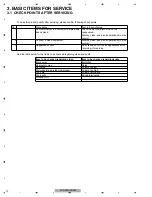
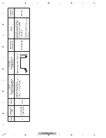
Step
1
Composite
video level
Input test pin : AUX1V
Signal : 100IRE(white 100 %)
Level : 1.0 Vp-p(75 ohm)
Adjustment
item
Measuring
instruments
Specs
Adjusting
point
Input
(input test pin,specs,
other conditions)
Output
(measuring point,
waveform)
Measuring point : OUT1V
Oscilloscope
1.00 Vp-p ± 0.03 Vp-p
Measure between the
sync tip and 100IRE
(top level).
VR1241
Mode
VTR
Measuring conditions: Select
the 75 ohm terminal on the measuring
instrument.
Summary of Contents for AVD-W9000
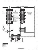
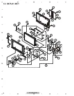
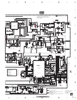
Page 28: ...AVD W9000 UR 28 1 2 3 4 1 2 3 4 C D F A B E 9 2 DISPLAY ASSY B C D E ...
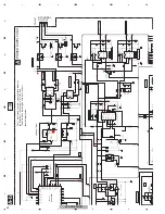
Page 30: ...AVD W9000 UR 30 1 2 3 4 1 2 3 4 C D F A B E 9 3 POWER SUPPLY ASSY A ...
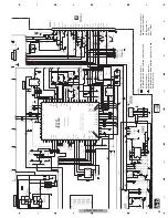
Page 55: ...AVD W9000 UR 55 5 6 7 8 5 6 7 8 C D F A B E ...
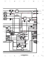
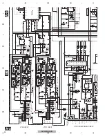
Page 66: ...AVD W9000 UR 66 1 2 3 4 1 2 3 4 C D F A B E E E SERVICE UNIT VIDEO PCB ...
Page 67: ...AVD W9000 UR 67 5 6 7 8 5 6 7 8 C D F A B E E SIDE B ...

